Deciding whether a producing well has a tubing leak or packer leak requires more than a rise in tubing–casing annulus pressure. Both can provide communication with the same annulus, while other completion paths, deliberately applied pressure and temperature effects can produce similar surface observations. Diagnosis requires the actual completion layout, a pressure and operating history, and evidence that narrows the suspected path. [1, 2, 3]
The useful question is not simply “Which gauge increased?” It is: which two spaces may communicate, where could the connection be, and what evidence distinguishes the alternatives? This article develops that reasoning for producing wells. Its diagrams and worked examples are educational constructions, not records from a particular well.
Identify the Annulus and Its Intended Connections
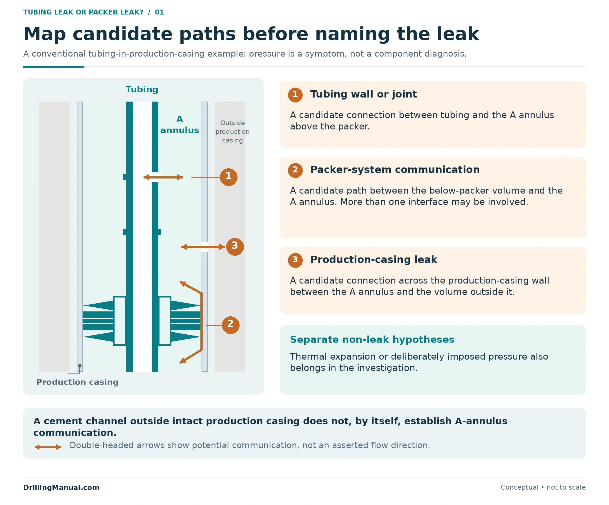
Begin with the as-built completion and the pressure-monitoring point. In the conventional examples below, the A annulus is the space between production tubing and production casing above the production packer. Confirm the actual well’s naming and connections; a gauge at a different port may observe a different volume. The completion drawing must show the packer, tubing seals, communication devices, control lines and relevant wellhead interfaces. [1, 4]
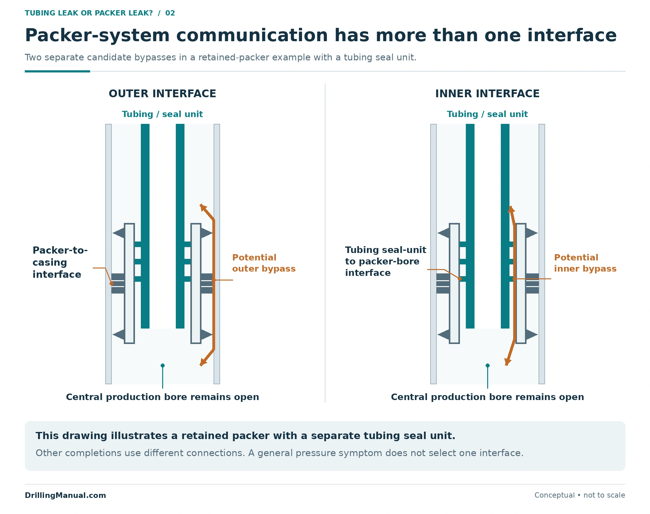
A production packer and its tubing connection create separate interfaces. The packer’s outer sealing system acts against the casing. Some completion arrangements also use a tubing seal unit inside the packer bore. Equipment above and below those interfaces determines which paths are possible. The production packer guide explains the basic components. [4]
The installed operating arrangement matters equally. A gas-lift completion intentionally uses annulus pressure and a designed route into the tubing. A sliding sleeve can also provide a communication route. An observed connection must therefore be compared with the intended equipment state before it is called a defect. [1, 4]
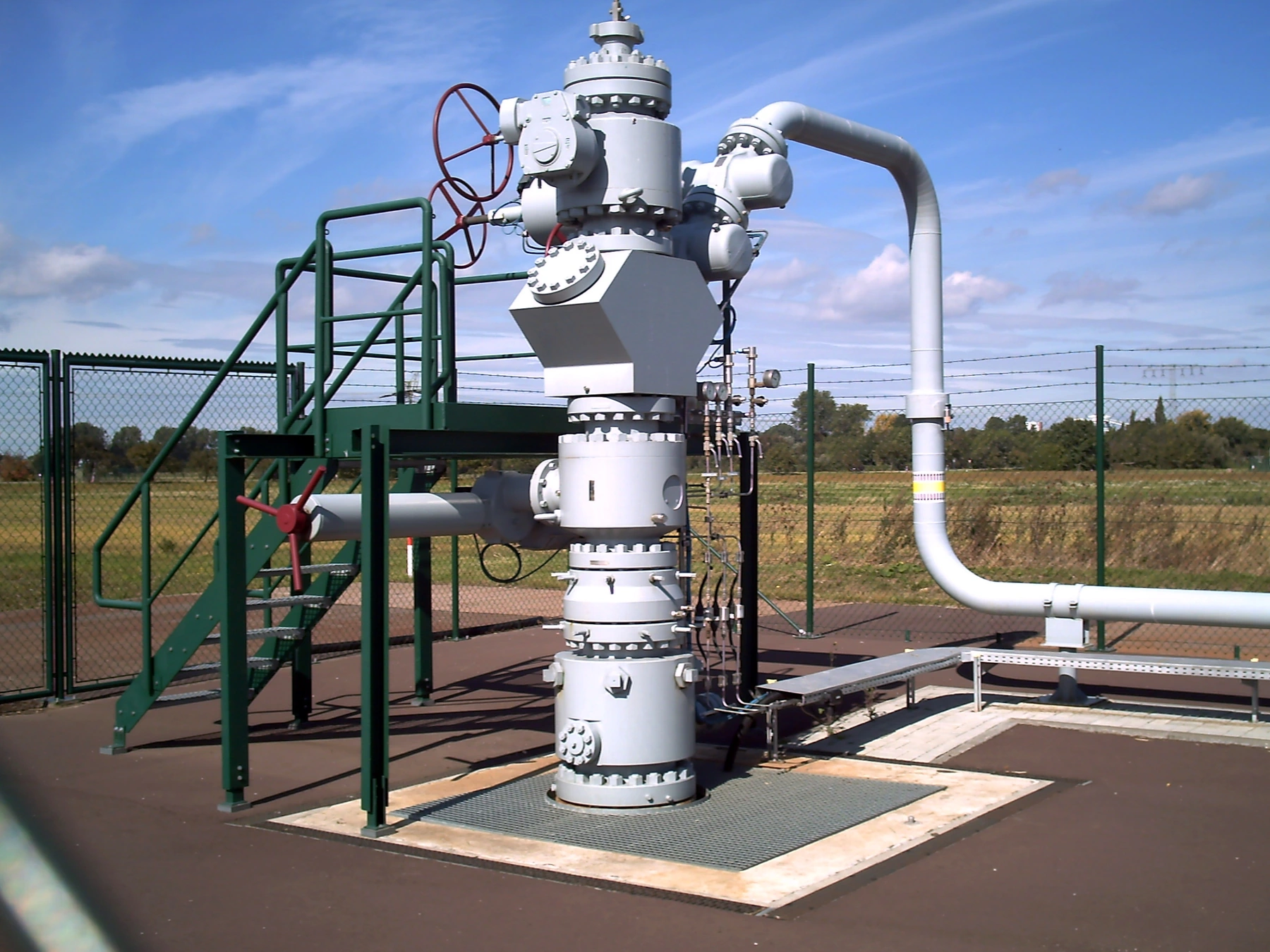
Photo: HartmannValves / Wikimedia Commons, CC BY 3.0. Resized and converted from JPEG to WebP; no crop or content alteration.

Does Annulus Pressure Always Mean a Leak?
No. The ISO 16530-1:2017 reference separates deliberately imposed pressure, thermally induced pressure and sustained casing pressure. These categories frame the investigation; they do not locate a failed component. Review the pressure source alongside the operating and temperature history. [1]
- Imposed pressure: confirm the intended operating purpose, such as gas lift, and the recorded equipment configuration.
- Thermal pressure: temperature changes can alter pressure in a trapped annulus volume. A thermal explanation still requires assessment against the well’s applicable limits.
- Sustained casing pressure: the reference describes pressure that rebuilds after bleed-off and cannot be attributed to imposed or thermal effects. Its interpretation also depends on the completion; some designs allow communication that a packed completion is intended to prevent.
Consequently, a pressure increase during start-up is not enough to prove leakage, and a rebuild record is not enough to identify a tubing joint or packer seal. The operator defines the investigation and pressure limits for the well. The broader well integrity guide covers the management framework. [1]
Tubing Leak or Packer Leak: Compare the Possible Paths
Perrin lists tubing failures and failures of packer, locator, movement-joint and circulating-device seals among completion problems. Schlumberger’s cased-hole reference also distinguishes tubing leaks, casing leaks, packer leaks and communication behind casing. The phrase “packer leak” can therefore be too broad for selecting a repair. [2, 3]
| Candidate path | What may communicate | What the diagnosis still needs |
|---|---|---|
| Tubing wall or connection above the packer | Tubing bore and surrounding A annulus | Depth and component evidence that separate a tubular defect from an installed communication device |
| Packer’s outer sealing system | Spaces above and below the packer around its outer boundary | Evidence that distinguishes this interface from the tubing seal connection |
| Tubing seal unit or associated packer-bore interface | Spaces separated by that seal arrangement | The actual seal/anchor design and evidence locating communication within that assembly |
| Valve, sleeve or gas-lift route | The spaces connected by the installed device | Its intended position and function, plus evidence of unintended communication |
| Wellhead, hanger seal or control/injection line | The particular spaces connected by that interface | A verified surface/line configuration and suitable interface-specific evidence |
| Production casing or a wider external path | A annulus and a volume outside that casing, if a connecting breach exists | Evidence for the complete path; a cement channel alone does not establish communication into A annulus |
This is a map of hypotheses, not a list of equally likely failures. Some paths do not exist in a particular completion. Others may operate as designed. Remove impossible paths using the as-built arrangement before interpreting a pressure trend. [1, 2, 4]
Separate the Packer Element From the Tubing Seals
In a retained-packer completion, the production tubing can seal inside the packer’s bore while the packer remains attached to the casing. Communication near that assembly may involve the tubing seal unit, its mating bore or the outer packer sealing system. “At packer depth” does not identify which interface has failed. [4]
The permanent packer and seal-assembly guide and polished bore receptacle guide provide the component terminology. Use the installed model and connection drawing when translating a localized anomaly into a component hypothesis. Not every packer arrangement contains the removable seal unit shown here. [4]
Surface Pressure Does Not Determine the Downhole Differential
Pressure at a possible communication point depends on the pressures and fluid columns on both sides. A higher tubing pressure at surface does not guarantee a higher tubing pressure at every depth. The following original calculation applies the book’s hydrostatic relationship to two initially isolated liquid columns. [4]
Assume static, uniform liquids; a common surface datum; tubing surface pressure of 700 psig with 8.0-ppg fluid; and annulus surface pressure of 500 psig with 10.0-ppg fluid. Ignore gas, fluid interfaces, temperature-dependent density changes and friction. No communication path is assumed to be open.
P at depth = P at surface + 0.052 × fluid density × TVD, with pressure in psi, density in ppg and true vertical depth in feet.
| TVD below the common datum | Tubing pressure | Annulus pressure | Annulus minus tubing |
|---|---|---|---|
| 0 ft | 700 psig | 500 psig | −200 psi |
| 1,000 ft | 700 + 0.052 × 8 × 1,000 = 1,116 psig | 500 + 0.052 × 10 × 1,000 = 1,020 psig | −96 psi |
| 3,000 ft | 700 + 0.052 × 8 × 3,000 = 1,948 psig | 500 + 0.052 × 10 × 3,000 = 2,060 psig | +112 psi |
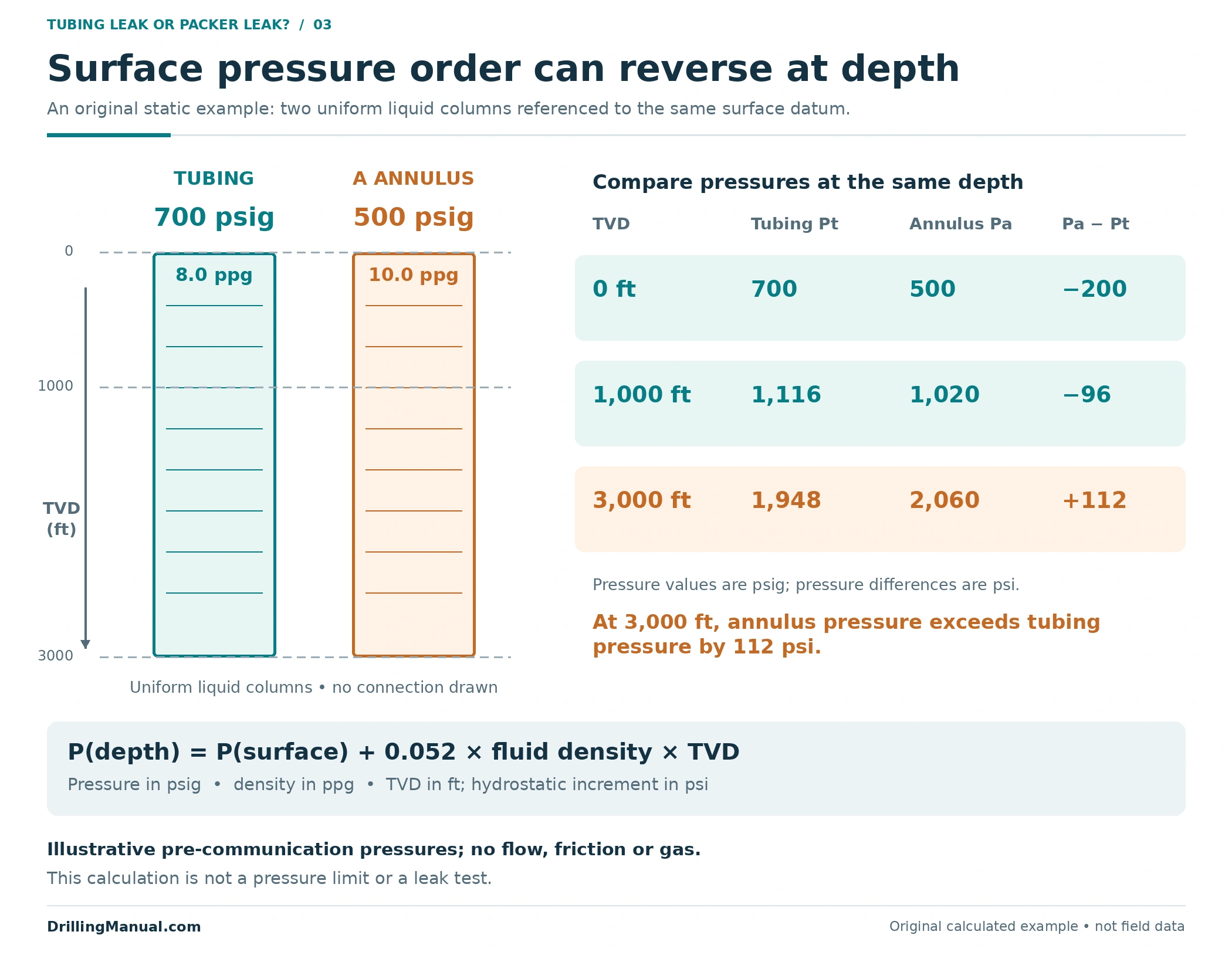
At the assumed 3,000-ft depth, the annulus side is initially 112 psi higher despite its lower surface reading. That establishes the initial local differential in this simplified example; it does not establish that a leak exists or predict its rate. If a path opens, fluid movement changes the assumed static state.
Real flowing or multiphase wells require the relevant fluid distribution, pressure losses and operating conditions. Use this calculation to understand why the local differential matters, not to derive a test pressure, allowable annulus pressure or field operating limit. Pressure and temperature also affect tubing mechanics; those effects are treated separately in the tubing movement calculations article. [4]
Build the Evidence Record Before Naming the Failed Component
The pressure record needs an operating context. ISO 16530-1:2017 identifies fluid types and volumes, fluid properties, pressure trends, monitoring-equipment checks and operational changes as relevant records. Both increases and decreases belong in the assessment. Its investigation discussion also recognizes that fluid samples can help identify a pressure source. [1]
For this article’s diagnostic comparison, organize those records into six groups: the current completion and monitored ports; operating and temperature history; fluid inventories and densities; pressure measurements with a common time reference; the configuration and results of approved tests; and depth-correlated survey evidence. This organization is an original editorial framework.
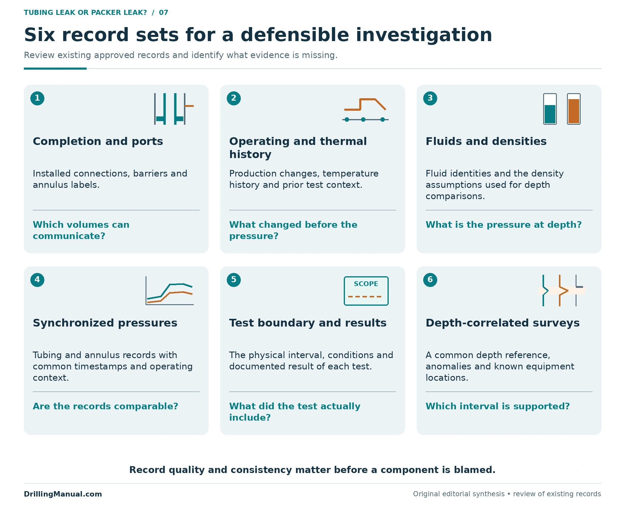
Separate observation from interpretation. “A-annulus pressure changed when production changed” is an observation. “The packer element is leaking” is a component-level conclusion. Between them lie alternative explanations, including thermal effects, intended communication and another failed interface. The useful report states which alternatives the evidence has actually excluded. [1, 2]
Review and investigation methods must follow the well-specific approved program. This article does not prescribe a bleed-down sequence, a pressure change, a test duration or a numerical acceptance limit.
Which Measurements Help Locate a Tubing or Packer Leak?
Production logs combine measurements because individual channels answer different questions. A survey may locate evidence of fluid movement, estimate a contribution or characterize the fluid. None of those results should silently become proof of a specific failed seal. Schlumberger’s reference explains how temperature, noise and flow measurements complement one another. [2]
| Evidence | How it helps | Important limit |
|---|---|---|
| Pressure and operating history | Relates changes to the observed spaces and operating state | A correlated response alone may not distinguish pressure communication from a shared thermal cause |
| Temperature survey | Detects thermal departures associated with fluid movement, including some movement behind casing | The response depends on the flow and thermal conditions; one departure is not a universal leak signature |
| Noise survey | Detects acoustic energy associated with fluid movement and can help narrow its depth | Tool movement, fluid environment, source distance and tool contact affect interpretation |
| Flowmeter with supporting fluid measurements | Helps identify changes in flow and place an entry within the measured profile | Multiphase distribution, sensor response and the flow being sampled affect the result |
| Fluid composition and documented sampling | Can help associate annulus fluid with a possible source | A source indication does not, by itself, locate the connecting hole or failed interface |
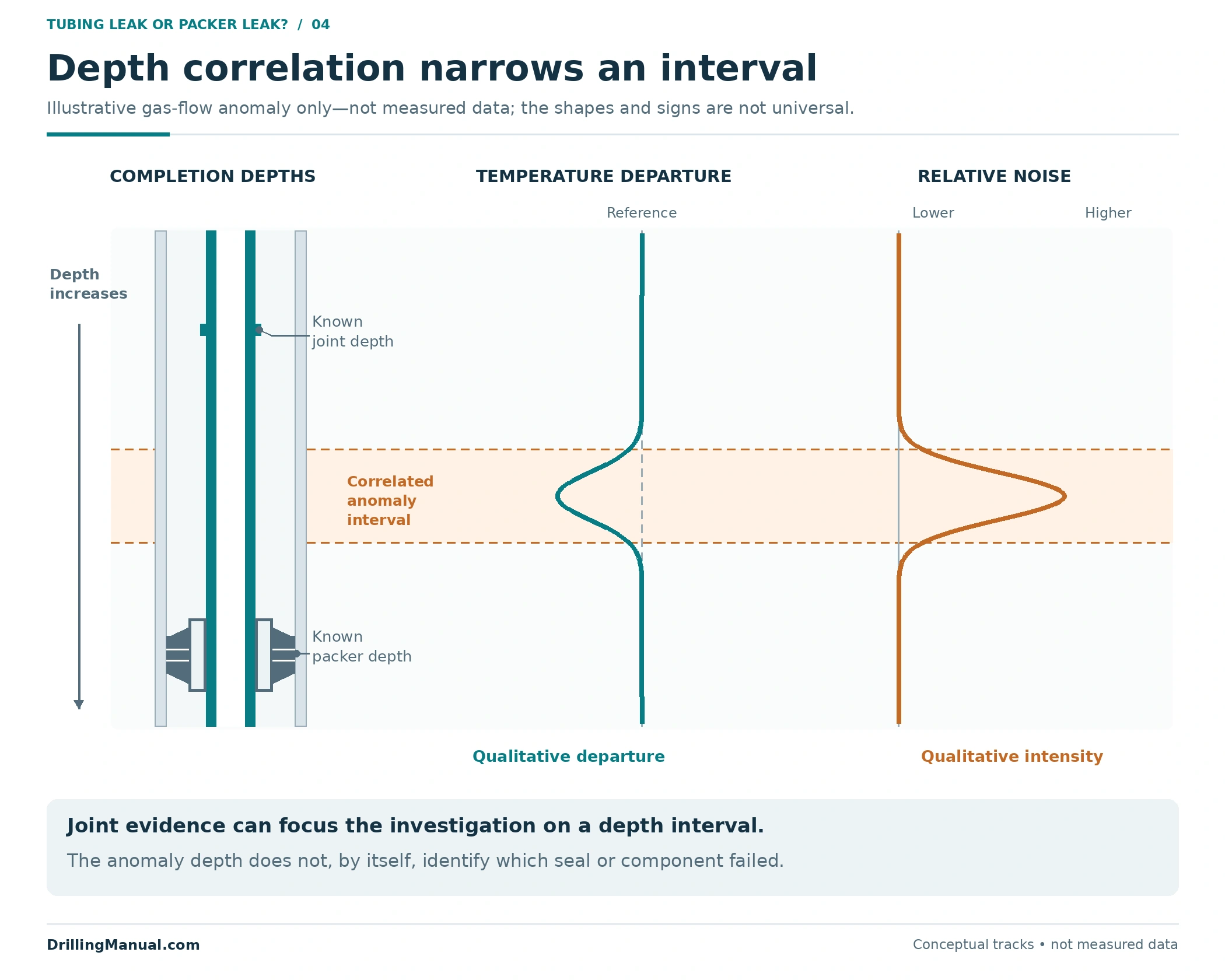
A temperature tool responds to thermal conditions; a passive noise tool responds to sound generated in or around the well. Noise is not a direct map of hole size. The cased-hole reference specifically describes limitations on deriving flow rate from noise and explains why other measurements are generally preferable for quantification. [2]
Compare surveys with their recorded well conditions. A feature observed while flowing may change during a shut-in survey because the fluid movement and thermal state change. Depth correlation and repeatability matter when comparing that feature with a tubing connection, sleeve or packer assembly. [2]
Photo: Joshua Doubek / Wikimedia Commons, CC BY-SA 3.0. Resized and converted from JPEG to WebP; no crop or content alteration.

The Fluid Source and the Wellbore Entry Can Be Different Depths
Fluid can travel behind casing before entering the casing bore at another depth. The cased-hole reference illustrates cases in which the flow and fluid-density changes identify an entry while temperature information helps explain movement along an external path. The entry is therefore not automatically the original source interval. [2]
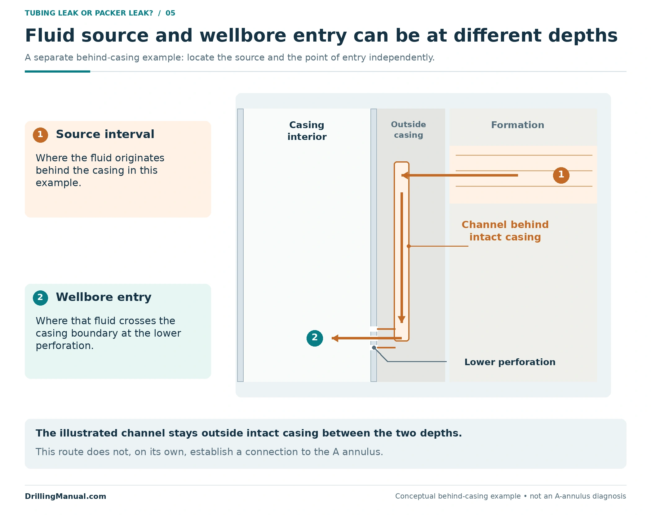
This behind-casing example explains a localization limit. It does not, by itself, establish an A-annulus leak: the proposed path still has to connect to the monitored A-annulus volume. A cement bond log addresses cement evaluation; evidence of active fluid movement answers a different part of the investigation. [1, 2]
What Does a Successful Pressure Test Actually Cover?
Interpret a recorded test against its stated boundary, applied differential and equipment configuration. If a verified isolation point excludes the packer and lower completion from a tubing test, that result cannot be used as evidence that the excluded packer has passed. The diagram below is an original illustration of this scope limit, not an instruction for configuring a test. [1, 4]
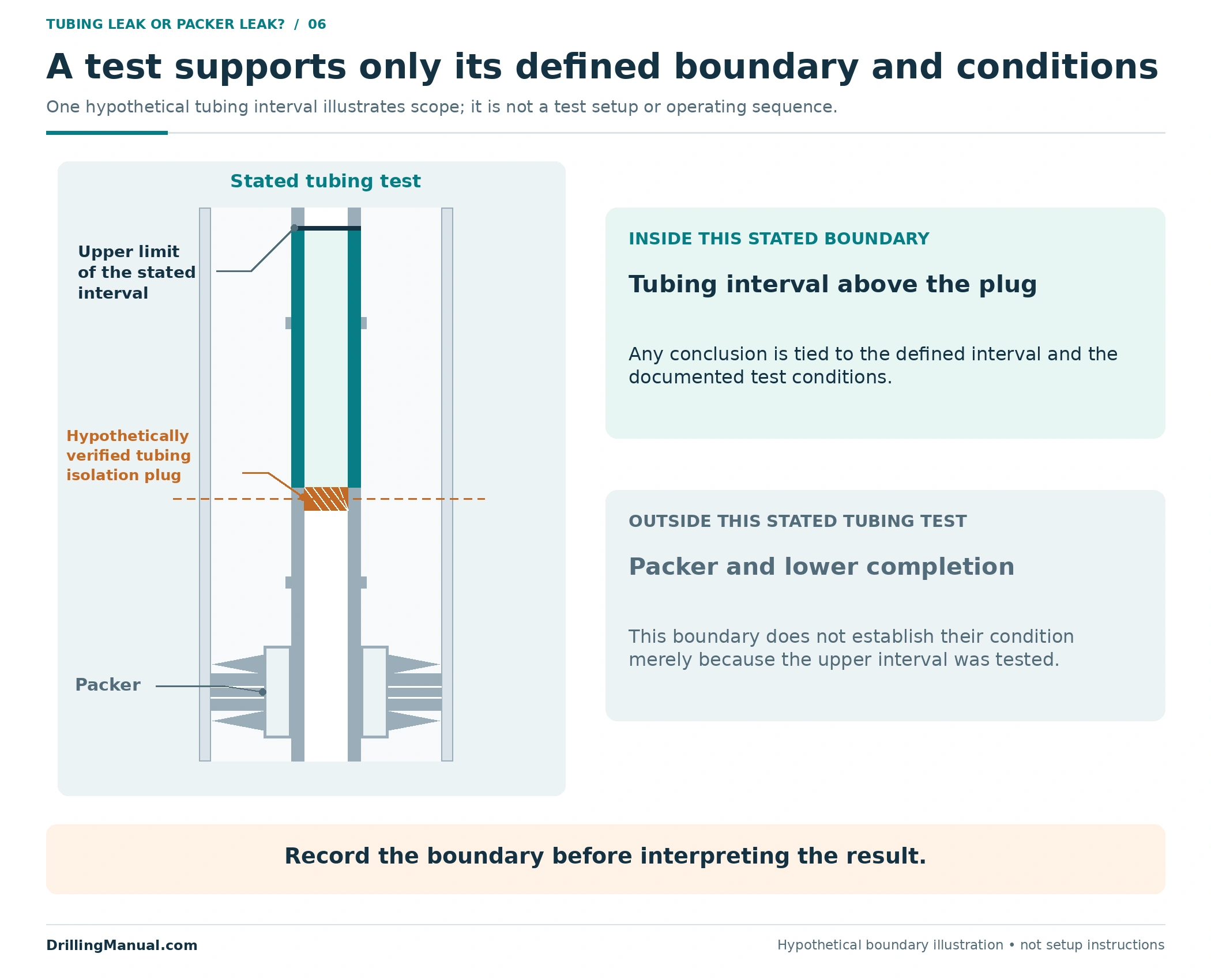
The same discipline applies to a survey with no detected anomaly. Record the conditions and sensitivity relevant to that survey. A quiet noise record or a weak temperature response does not independently prove that every candidate path is closed under every operating condition. The sources describe measurements that depend on fluid movement and the surrounding environment. [2]
Worked Comparison: Similar Annulus Symptoms, Different Evidence
Consider two hypothetical producing wells with the same conventional completion layout and unexplained A-annulus pressure changes. Initial review has not established an imposed-pressure explanation or completed the thermal assessment. At this stage, neither well has a confirmed tubing or packer leak.
| Evidence developed later | Well A | Well B |
|---|---|---|
| Depth-correlated survey | A repeatable joint temperature/noise feature is above the packer, near an upper completion component | The relevant feature is near the packer assembly |
| Connection review | Check the tubular, connection and any installed communication device at that depth | Distinguish the tubing seal-unit interface from the packer’s outer interface |
| Defensible interim conclusion | The upper-completion interval deserves focused investigation | The packer-system interval deserves focused investigation |
| Conclusion not yet established | The exact failed part and its repair scope | Which packer-system interface failed, or whether the packer body must be recovered |
The new evidence changes the location of the investigation. It does not establish which component failed within that interval. A stronger diagnosis adds the independent boundary, component or inspection evidence needed to choose between the remaining paths. This comparison is original reasoning built from the books’ completion and logging distinctions, not a claim about a documented field job. [2, 3, 4]
Turn the Diagnosis Into a Defined Repair Objective
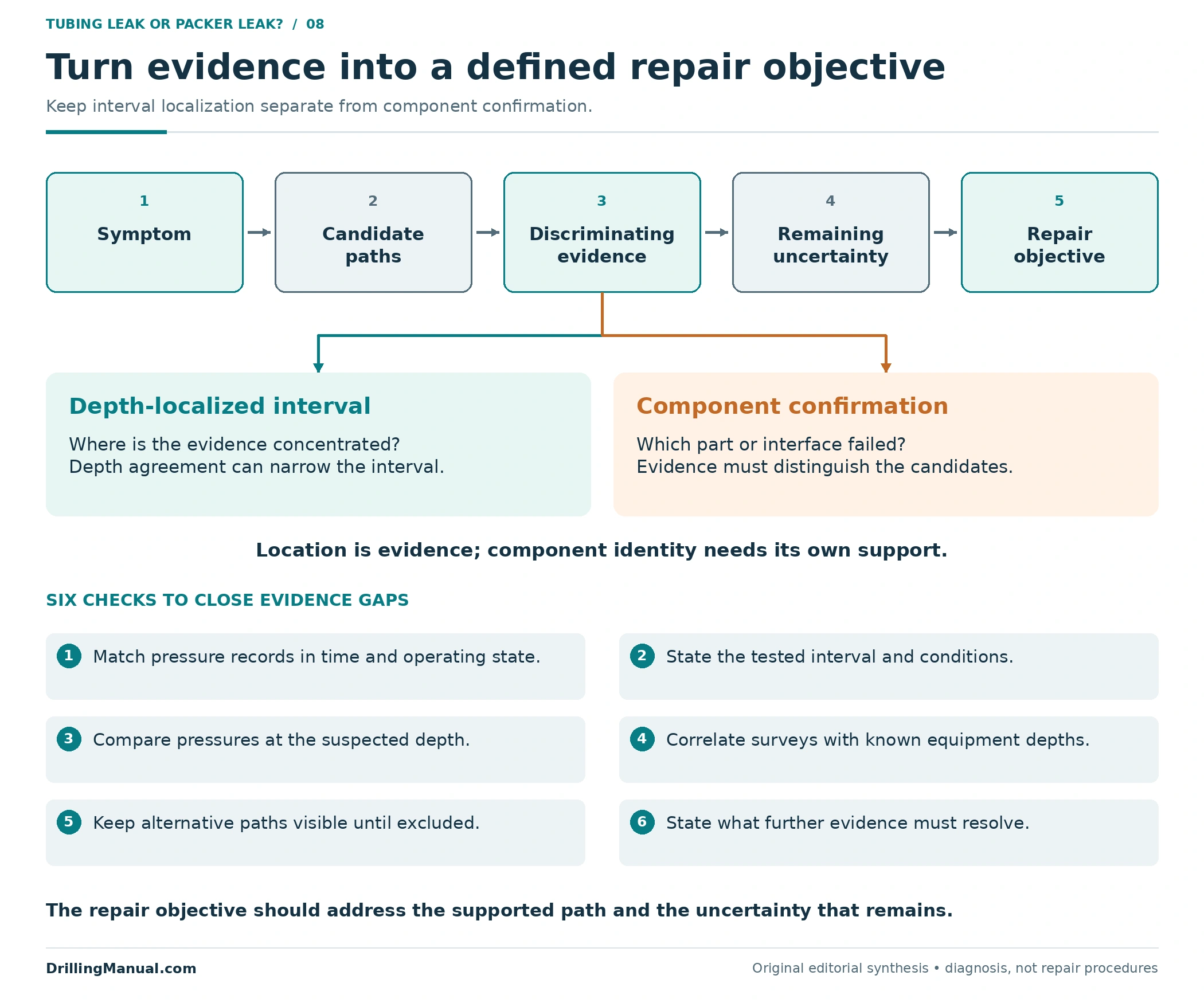
A useful handover names the affected spaces, the best-supported path or interval, the evidence, and the uncertainty still remaining. It also states what the next work must demonstrate. Keep a suspected interval, a confirmed failed component and a verified restored function as distinct findings.
A photograph of recovered tubing can document a visible opening or damage. It cannot retrospectively prove that every earlier pressure observation came from that defect, or establish the condition of equipment still downhole. Preserve the connection between the measured evidence, recovered inventory and revised completion record. This is an editorial application of the references’ distinction between equipment condition and recovery scope. [3, 4]
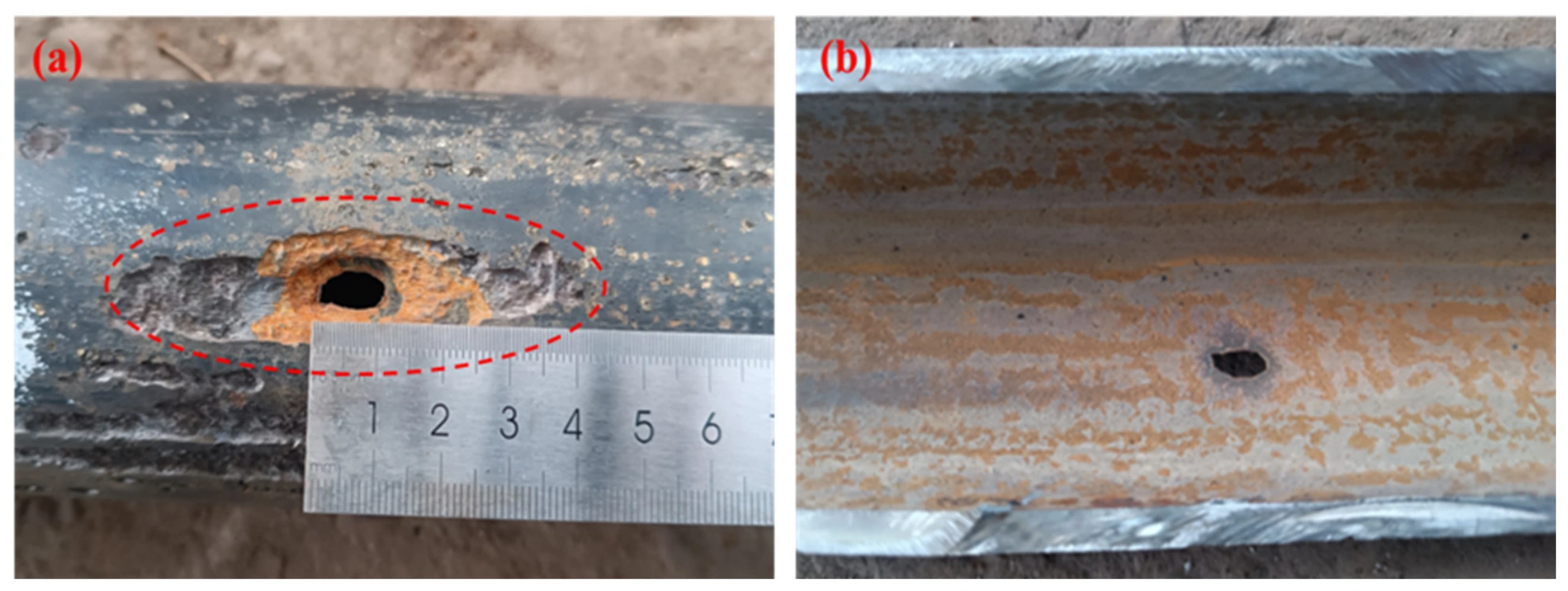
Photo: Ma et al., Energies (2026), Figure 1, CC BY 4.0. Converted from PNG to WebP; all panels, annotations and framing retained.
Repair access then follows the established objective. Replacing a tubing component, recovering a seal unit and retrieving a packer can require different scopes. The retrievable packer guide and workover operations guide provide that equipment and access context. Annulus pressure alone should not predetermine a full completion pull. [3, 4]
Frequently Asked Questions
Does Rising Annulus Pressure Prove a Packer Leak?
No. Review imposed pressure, thermal effects and the completion’s possible communication paths. Even a localized anomaly near the packer may involve its tubing seals rather than its outer sealing system. [1, 4]
Does Pressure Rebuilding After Bleed-Off Identify a Tubing Leak?
No. Rebuild behavior is part of investigating the pressure source. The reference’s sustained-pressure definition excludes imposed and thermal explanations, and still does not name the failed component. Such tests follow an operator-defined procedure. [1]
Can Fluid Move Into the Tubing When Annulus Pressure Is Lower at Surface?
It can be possible if the local annulus pressure is higher at the communication depth. Different fluid-column gradients can reverse the surface pressure ordering, as the static example shows. The actual well needs its own pressure and fluid assessment. [4]
Can a Temperature Log Locate a Leak by Itself?
It can supply useful localization evidence, but interpretation depends on the thermal and flow conditions. Combine it with the completion geometry and other measurements needed to distinguish the candidate paths. [2]
Does a Stronger Noise Signal Mean a Larger Leak Rate?
Not as a general rule. Source distance, fluid environment, tool contact and other factors affect the response. The reference describes limitations on quantitative noise interpretation and generally favors other sensors for flow-rate determination. [2]
Does Normal Annulus Pressure Prove That the Completion Is Intact?
A single normal reading is insufficient. The reference recognizes that a lack of positive pressure-monitoring evidence can call for other integrity verification. Assess the monitored volume, history and operating conditions. [1]
What Annulus Pressure Is Acceptable During Investigation?
There is no universal value for this article to supply. Use the well’s applicable operating limits, equipment and formation constraints, and approved investigation program. Neither the hypothetical 112-psi differential nor any example pressure here is an acceptance criterion. [1]
Must the Tubing Be Pulled to Distinguish a Tubing Leak From a Packer Leak?
Not automatically. Existing records, suitable tests and downhole measurements can narrow the investigation before the repair-access decision. Whether recovery is required depends on the actual defect, available access and the evidence needed to complete the job. [2, 3]
Technical References
[1] ISO 16530-1:2017. Petroleum and natural gas industries — Well integrity — Part 1: Life cycle governance. Consulted reference copy, especially clause 9.5, printed pp. 56–58 / physical PDF pp. 64–66. Used for pressure-source categories, monitoring context and investigation limits. The article does not claim this edition establishes the current requirements for a particular operator or jurisdiction.
[2] Schlumberger. Cased Hole Log Interpretation: Principles/Applications. Copyright 1989; fourth printing, March 1997, as identified in the consulted copy. Printed p. 1-1 / physical PDF p. 12 for cement-evaluation scope; Chapter 4, especially printed pp. 4-1–4-3, 4-5, 4-7–4-8 and 4-16–4-19 / physical PDF pp. 68–70, 72, 74–75 and 83–86. Used for completion-flow problems and the roles and limitations of temperature, noise and supporting production-log measurements.
[3] Perrin, Denis, with Michel Caron and Georges Gaillot. Well Completion and Servicing. Editions Technip, English edition, 1999. Chapter 5, especially printed pp. 254–256 and 293–296 / physical PDF pp. 266–268 and 305–308. Used for completion-equipment failures, intervention objectives and condition-dependent recovery.
[4] Economides, Michael J.; Watters, Larry T.; and Dunn-Norman, Shari, editors. Petroleum Well Construction. John Wiley & Sons; consulted 903-page digital copy. Especially PDF pp. 429–432 for hydrostatic relationships, and pp. 500–504, 511, 513–514, 517–523, 543–545 and 628 for completion connections and devices. Page numbers refer to this digital copy. Only the hydrostatic relationship is used from the cementing example; its procedures and operating values are not adopted.
Engineering explanations come from these books and references. The numerical example, diagnostic comparisons, tables and diagrams are original educational constructions. Photograph sources and reuse licences are given in their captions.