This article covers all formulas that are used while well control situations on the drilling rig ( Check also: Drilling rigs Types).
Pressures Formulas
HYDROSTATIC PRESSURE (all depths TVD):
Constants:
- PPG x FT x .052 = PSI,
- SG x FT x .433 = PSI,
- SG x MT x 1.42 = PSI,
- PPG x MT x .171 = PSI,
- SG x MT x .098 = BARS,
- PCF x FT x .0069 = PSI,
- SG x MT x .1 = kg/cm2
- SG x MT x 9.8 = kPa,
- Kg/m3 x MT ÷ 102 = kPa,
- PPG x MT x 1.176 = kPa,
- PPG x FT x .358 = kPa,
PRESSURE, psi = Mud Weight x Constant x Depth, (TVD)
PRESSURE GRADIENT, psi/ft
= Mud Weight x Constant
OR
= Pressure, psi ÷TVD, ft
MUD WEIGHT
= Pressure, psi ÷ TVD, ft ÷ Constant
OR
= Pressure Gradient, psi/ft ÷ Constant
FORCE
= Pressure x Area
LENGTH TO CREATE A PRESSURE, ft
= Pressure, psi ÷ Gradient psi/ft
OR
= Pressure, psi ÷ Mud Weight ppg ÷ .052
FORMATION PRESSURE, psi
= (Mud Wt, ppg x .052 x Bit TVD, ft) + SIDPP, psi
BUOYANCY FACTORS AND MUD WEIGHT EQUIVALENTS
| PPG | BUOYANCY FACTOR | PSI/FT | SG | Kg/M3 | PCF |
| 8.34 | .873 | .433 | 1.0 | 1000 | 62.4 |
| 8.4 | .872 | .436 | 1.01 | 1008 | 62.8 |
| 8.6 | .868 | .447 | 1.03 | 1032 | 64.3 |
| 8.8 | .865 | .457 | 1.06 | 1056 | 65.8 |
| 9.0 | .862 | .468 | 1.08 | 1080 | 67.3 |
| 9.2 | .860 | .478 | 1.10 | 1104 | 68.8 |
| 9.4 | .856 | .488 | 1.13 | 1128 | 70.3 |
| 9.6 | .853 | .499 | 1.15 | 1152 | 71.3 |
| 9.8 | .850 | .509 | 1.18 | 1176 | 73.3 |
| 10.0 | .847 | .519 | 1.20 | 1200 | 74.8 |
| 10.2 | .844 | .530 | 1.22 | 1224 | 76.3 |
| 10.4 | .841 | .540 | 1.25 | 1248 | 77.8 |
| 10.6 | .839 | .551 | 1.27 | 1272 | 79.3 |
| 10.8 | .836 | .561 | 1.29 | 1296 | 80.8 |
| 11.0 | .833 | .571 | 1.32 | 1320 | 82.3 |
| 11.2 | .829 | .582 | 1.34 | 1344 | 83.8 |
| 11.4 | .826 | .594 | 1.37 | 1368 | 85.3 |
| 11.6 | .823 | .603 | 1.39 | 1392 | 86.8 |
| 11.8 | .820 | .613 | 1.41 | 1416 | 88.3 |
| 12.0 | .817 | .623 | 1.44 | 1440 | 89.8 |
| 12.2 | .814 | .634 | 1.46 | 1464 | 91.3 |
| 12.4 | .810 | .644 | 1.49 | 1488 | 92.8 |
| 12.6 | .808 | .655 | 1.51 | 1512 | 94.3 |
| 12.8 | .804 | .665 | 1.53 | 1536 | 95.8 |
| 13.0 | .801 | .675 | 1.56 | 1560 | 97.3 |
| 13.2 | .798 | .686 | 1.58 | 1584 | 98.7 |
| 13.4 | .795 | .696 | 1.61 | 1608 | 100.3 |
| 13.6 | .792 | .706 | 1.63 | 1632 | 101.8 |
| 13.8 | .789 | .717 | 1.65 | 1656 | 103.3 |
| 14.0 | .786 | .727 | 1.68 | 1680 | 104.8 |
| 14.2 | .783 | .738 | 1.70 | 1704 | 106.3 |
| 14.4 | .780 | .748 | 1.73 | 1728 | 107.8 |
| 14.6 | .777 | .758 | 1.75 | 1752 | 109.3 |
| 14.8 | .774 | .769 | 1.77 | 1776 | 110.8 |
| 15.0 | .771 | .779 | 1.80 | 1800 | 112.3 |
| 15.2 | .768 | .790 | 1.82 | 1824 | 113.8 |
| 15.4 | .765 | .800 | 1.85 | 1848 | 115.3 |
| 15.6 | .763 | .810 | 1.87 | 1872 | 116.8 |
| 15.8 | .759 | .821 | 1.89 | 1896 | 118.3 |
| 16.0 | .755 | .831 | 1.92 | 1920 | 119.8 |
| 16.3 | .751 | .848 | 1.96 | 1956 | 122 |
| 16.6 | .746 | .862 | 1.99 | 1992 | 124 |
| 17.0 | .740 | .883 | 2.04 | 2040 | 127 |
| 17.3 | .735 | .900 | 2.08 | 2076 | 130 |
| 17.6 | .731 | .914 | 2.11 | 2112 | 132 |
| 18.0 | .725 | .935 | 2.16 | 2160 | 135 |
| 18.3 | .720 | .952 | 2.20 | 2196 | 137 |
| 18.6 | .716 | .966 | 2.23 | 2232 | 139 |
| 19.0 | .710 | .987 | 2.28 | 2280 | 142 |
Killing Formulas For Well Control
These formulas are used in kill sheet calculations. Assume the following values to help you more understand such calculations
| Bit TVD | = | 10,000 ft |
| Mud Weight | = | 10.6 ppg |
| SIDPP | = | 800 psi |
| Slow Circulating Rate Pressure @ 40 SPM | = | 900 psi |
KILL MUD WEIGHT, ppg
= (SIDPP, psi ÷ .052 ÷ TVD, ft) + Mud Wt, ppg
= (800 ÷ .052 ÷ 10,000) + 10.6
= 1.54 + 10.6
= 12.14 ppg
ICP (Initial Circulating Pressure)
= Slow Circulating Rate Pressure, psi + SIDPP, psi
= 900 + 800
= 1,700 psi
FCP (Final Circulating Pressure)
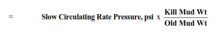
= Slow Circulating Rate Pressure, psi x Kill Mud Wt ÷ Old Mud Wt
= 900 x 12.14 ÷ 10.6
= 900 x 1.1453
= 1,031 psi
Note: After a correct Start-Up the actual SCR pressure = Actual ICP – SIDPP
If using units other than PPG, Feet, and PSI then refer to page 4.1 for constants.
STEP DOWN CHART
Used to calculate pressure drop versus strokes as KILL MUD is pumped to the DRILLING BIT. There are 2 ways this can be done:-
FIXED STROKE INTERVAL OR FIXED PRESSURE INTERVAL
FIXED STROKE INTERVAL
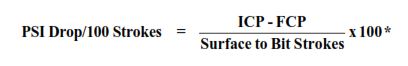
(This number should be replaced if you use a different stroke interval e.g. 50, 200, 300, etc)
FIXED PRESSURE INTERVAL
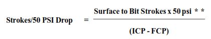
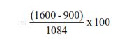
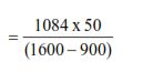
Strokes/50 PSI Drop = Surface to Bit Strokes x 50 psi ÷ (ICP – FCP)
** (This number should be replaced if you use a different pressure interval e.g. 40, 60, etc)
EXAMPLE: ICP = 1600, FCP = 900 – Surface to Bit Strokes = 1084
Fixed Strokes :
= 65 psi approx
| STROKES | PSI | |
| 0 | 1600 | (ICP) |
| 100 | 1535 | |
| 200 | 1470 | |
| 300 | 1405 | |
| 400 | 1340 | |
| 500 | 1275 | |
| 600 | 1210 | |
| 700 | 1145 | |
| 800 | 1080 | |
| 900 | 1015 | |
| 1000 | 950 | |
| 1084 | 900 | (FCP) |
Fixed Pressure:
= 77 strokes approx.
| STROKES | PSI | |
| 0 | 1600 | (ICP) |
| 77 | 1550 | |
| 154 | 1500 | |
| 231 | 1450 | |
| 308 | 1400 | |
| 385 | 1350 | |
| 462 | 1300 | |
| 539 | 1250 | |
| 616 | 1200 | |
| 693 | 1150 | |
| 770 | 1100 | |
| 847 | 1050 | |
| 924 | 1000 | |
| 1001 | 950 | |
| 1084 | 900 | (FCP) |
With Kill Mud at the drilling bit, the pressure is then held constant for the remainder of Kill. Used for WAIT and WEIGHT Method.
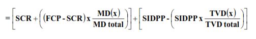
DEVIATED STEP-DOWN CALCULATION – Well control Formulas
The following can be used to calculate step-down pressure on a deviated well (directional drilling).
- SIDP = 300 psi
- ICP = 800 psi
- FCP = 550 psi
- SCR = 500 psi
| MD 0 | 1000’ | 2000’ | 3000’ | 4000’ | 5000’ |
| TVD 0 | 1000’ | 2000’ | 2500’ | 3000’ | 3400’ |
P circ (x) = Pressure to circulate at depth of interest
For x = 3000 ft TVD (4000 ft MD)
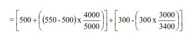
= [500 + (50 x .8)] + [300 – (300 x .8823)]
= (500 + 40 ) + (300 – 265 )
= 540 + 35
= 575 psi
The equivalent using Vertical Step Down calculation = 600 psi
TRIP MARGIN
Approximate Mud Wt. value to be added after killing a kick.
Yield Point of Mud = 14
Hole Diameter (Dh) = 12¼”
Pipe Outside Diameter (dp) = 5”
TRIP MARGIN, ppg
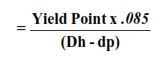

= 0.164 ppg
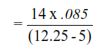
PSI/BARREL
In well control formulas, A factor represents the pressure exerted by 1 barrel of mud in the annulus. (Can be used for inside Pipe by using Pipe Capacity instead of Annular Volume).
Mud Weight = 11 ppg
Annular Volume = .1215 bbls/ft
PSI/BARREL
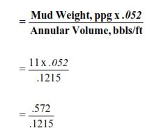
= 4.7 psi/barrel
MUD TO BLEED DUE TO BUBBLE RISE (VOLUMETRIC)
Method of bringing gas to surface without SIDPP reading and unable to circulate. (Check Volumetric Method).
Pressure rise allowed while well is shut in (check shut-in procedure) = 100 psi
Current psi/barrel factor = 14 psi (see above drilling formulas) VOLUME TO BLEED, bbls
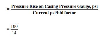
= 7 barrels
- If SICP = 800 psi, Allow 50 to 100 psi for Safety.
- Let SICP rise with well shut-in due to gas migration to 800 + Safety, e.g. 875 psi.
- Allow SICP to continue to rise to 875 + 100 = 975 psi.
- At 975 psi carefully manipulate choke to maintain 975 psi while bleeding off 7 barrels of mud (see above answer). Once 7 bbls have been bled, shut-in and allow SICP to rise to 975 + 100 = 1075. Again continue to hold at 1075 psi while bleeding 7 bbls.
- The process is repeated until gas arrives at the choke. Shut-in and remove gas by Lubricating Method.
COMBINED STRIPPING AND VOLUMETRIC WELL CONTROL FORMULA
The following calculations are used for stripping pipe in the hole when influx migration is a potential problem.
| Vk | = | Kick Volume, bbls |
| A1 | = | Open Hole Capacity, bbls/ft |
| A2 | = | Drill Collar to Open Hole Capacity, bbls/ft |
| V1 | = | Closed-End Displacement of 1 stand of drill pipe, bbls |
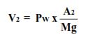
| V2 | = | Volume to Bleed, bbls |
| Mg | = = | Mud Gradient, psi/ft |
| Ig | = | Influx Gradient, psi/ft |
| SICP | = | Shut-in Casing Pressure, psi |
| Pw | = | Chosen Working Pressure, psi |
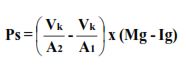
| Ps | = | Safety Pressure for Hydrostatic Pressure lost when BHA penetrates kick, psi |
| Pchoke | = | Choke Pressure Reading, psi |
Step 1 Calculate Ps, psi
Step 2 Choose Pw – Between 50 and 200 psi
Step 3 Calculate V2 bbls
Step 4 Strip into the hole without bleeding mud, until SICP increases to Pchoke1.
Pchoke1 = SICP + Ps + Pw
Step 5 Continue stripping in the hole holding casing pressure constant at Pchoke1. This will require mud to be bled from the well. Fill pipe regularly.
Step 6 The amount of mud gained in the Trip Tank over and above the drill pipe closed-end displacement (V1) will be the effect of gas expansion. (Some rigs have a Stripping Tank to allow for bleed-off of V1 every stand).
Step 7 When gain in Trip Tank due to gas expansion equals V2, continue to strip with the choke closed to build casing pressure up to Pchoke2.
Pchoke2 = Pchoke1 + Pw
Step 8 Continue stripping in hole holding casing pressure constant at Pchoke2.
Step 9 Repeat Steps 6, 7 and 8 (increasing Pchoke by Pw each time V2 is measured in Trip Tank) until back to bottom.
Step 10 Kill well as per standard well control techniques.
INFLUX HEIGHT/GRADIENT WELL CONTROL FORMULAS
INFLUX HEIGHT
| SIDPP | = | 800 psi |
| SICP | = | 900 psi |
| Collar Length | = | 538 ft |
| Annular Volume around Collars | = | .0836 bbls/ft |
| Annular Volume around Pipe | = | .1215 bbls/ft |
| Mud Weight | = | 10.6 ppg |
Total Annular Volume around Collars
= Collar Length, ft x Collar Annular Volume, bbls/ft
= 538 ft x .0836 bbls/ft
= 45 barrels
If INFLUX is LESS THAN volume around collars e.g. 20 barrels
INFLUX HEIGHT, ft
= Influx Volume, bbls ÷ Annular Volume around Collar bbls/ft
= 20 ÷ .0836
= 239 ft
If INFLUX is GREATER THAN volume around collars e.g. 75 bbls
INFLUX HEIGHT, ft
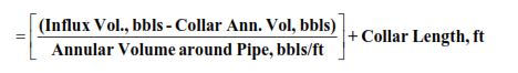
= (( (75 − 45) ÷ .1215 ))+ 538
= 247 + 538
= 785 feet
Using example on previous page where:
INFLUX GRADIENT, psi/ft
Influx Volume = 20 bbls
Influx Height = 239 ft
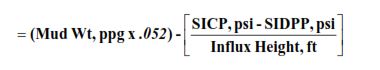
= (10.6 x .052) – (( (900 – 800) ÷ 239 ))
= 0.1328 psi/ft
Gradient of .2 or less = Gas – Gradient of .4 or more = Water
In between could be oil or a mixture of oil, water, and gas.
FRACTURE MUD WEIGHT/GRADIENT/PRESSURE FORMULAS
In well-control formulas, the fracture can be calculated using the pressure of the Leak Off Test.
- Float Shoe TVD = 8000 ft
- The leak-off test (LOT) was 2000 psi with 10.0 ppg mud in the hole.
FRACTURE MUD WEIGHT (MAX. EQUIV. MUD WT), ppg
= (LOT, psi ÷ Shoe TVD, ft ÷ .052) + Mud Wt, ppg
= (2000 ÷ 8000 ÷ .052) + 10.0
= 4.81 + 10.0
= 14.81 ppg
FRACTURE GRADIENT, psi/ft
= Fracture Mud Wt, ppg x .052
= 14.81 x .052
= .77 psi/ft
FRACTURE PRESSURE, psi
= Fracture Mud Wt, ppg x .052 x Shoe TVD, ft
= 14.81 x .052 x 8000 ft
= 6161 psi
Maximum pressure allowed on casing pressure gauge during operations.
(See above example)
| Fracture Mud Wt, ppg | = | 14.81 |
| Current Mud Wt, ppg | = | 10.6 ppg |
| Shoe TVD, ft | = | 8000 ft |
MAASP, psi
MAASP is the maximum allowable annular surface pressure
= (Frac. M. Wt, ppg – Current M.Wt, ppg) x .052 x Shoe TVD, ft
= (14.81 – 10.6) x .052 x 8000
= 4.21 x .052 x 8000
= 1751 psi
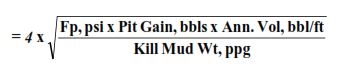
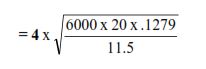
MAXIMUM SURFACE CASING PRESSURE
Approximate max. pressure at Casing Pressure gauge during a well kill operation. (Occurs when the well kick of gas (check also gas kick behavior and Migration) is almost at the surface). Using Wait and Weight.
| Formation Pressure (Fp) | = | 6000 psi (See page 4.1 for formula) |
| Pit Gain | = | 20 bbls |
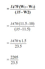
| Kill Mud Weight | = | 11.5 ppg |
| Surface Annular Volume | = | .1279 bbls/ft |
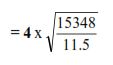
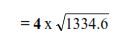
MAXIMUM CASING PRESSURE, psi
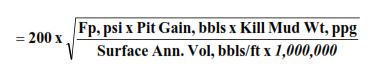
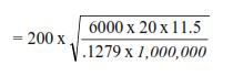
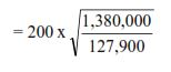
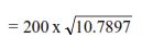
= 200 x 3.2848
= 657 psi
GAS KICK ASSOCIATED FORMULAS
Approximate volume gain at the surface due to gas expansion when circulating out a kick.
| Formation Pressure (Fp) | = | 6000 psi (see page 4.1 for formula). |
| Pit Gain | = | 20 bbls |
| Surface Annular Volume | = | .1279 bbls/ft |
| Kill Mud Wt | = | 11.5 ppg |
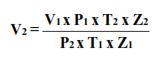
Volume Increase, BBLs =
= 4 x 36.5 = 146 bbls
GAS EXPANSION FOR To AND ‘Z’
This formula is based on Boyles Law and Charles Law, incorporating temperature and compressibility effects.
| To | = | F Deg + 460 |
| Z | = | Variable |
| P | = | psi + 14.7 |
GAS PERCOLATION RATE, ft/hr
How fast is gas percolating (migrating) up the hole.
| SIDPP at time Zero | = | 700 psi |
| SIDPP after 15 mins | = | 725 psi |
| Mud Weight | = | 10.5 ppg |
GAS PERCOLATION RATE, ft/hr
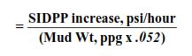
Increase per 15 minute interval = 25 psi
Increase per hour = 4 x 25 psi = 100 psi
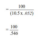
= 183 ft/hr
(SIDPP can be replaced with SICP)
DRILLING MUD-ASSOCIATED CALCULATIONS IN WELL CONTROL
BARITE REQUIRED
Amount added to mud to obtain kill weight.
| Original Mud Wt (W1) | = | 10 ppg |
| Kill Mud Wt (W2) | = | 11.5 ppg |
| Pit Volume | = | 840 barrels |
BARITE REQUIRED, pounds/barrel
= 94 pounds/barrel
TOTAL BARITE, pounds
= Mud Volume in Pits, bbls x Barite Required, lbs/bbl
= 840 x 94
= 78,960 pounds
VOLUME INCREASE/100 BARRELS OF MUD (due to adding barite)
= Barite Required, pounds/barrel ÷ 15
= 94 / 15
= 6.3 barrels/100 barrels of Mud (each 15 sacks of Barite added increases volume by approx 1 barrel).
TOTAL VOLUME after weight up
= (Barrels/ 100 barrels of Mud x Pit Volume ÷ 100 )+ Pit Volume
= (6.3 x 840 ÷ 100) + 840
= 5292 ÷ 100 + 840
= 53 + 840= 893 barrels
WELL CONTROL EQUIPMENT RELATED FORMULAS
USABLE FLUID VOLUME
Gallons of usable fluid in a single Accumulator Bottle. Multiply by the number of bottles to get the total.
USABLE FLUID VOLUME, gals/bottle
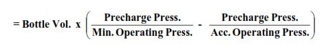
API RP53 gives recommended pressures for various units:-
- Precharge Pressure is normally 1000 psi
- Minimum Operating is normally 1200 psi
- Accumulator Operating Pressure is 3000 psi for most current units
- Check API RP 53 for 500 psi units
MINIMUM OPERATING PRESSURE
Minimum Operating Pressure is the pressure required to operate a BOP Ram against full-rated Wellbore Pressure.
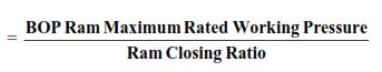
Note:- This calculated value of minimum operating pressure is normally applied in the Usable Fluid equation only when the result is greater than the API recommendation of 1200 psi
ACCUMULATOR VOLUME REQUIRED
GALLONS OF FLUID REQUIRED,
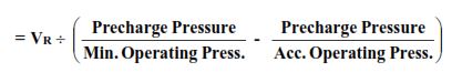
VR = Volume required to perform chosen functions, (either from API specs, client requirements or local regulations).
ACCUMULATOR PRECHARGE PRESSURE
A method of measuring average Accumulator Precharge Pressure by operating the unit with charge pumps switched off.
| Accumulator Starting Pressure (Ps) | = | 3000 psi |
| Accumulator Final Pressure (Pf) | = | 2200 psi |
| Total Accumulator Volume | = | 180 gallons |
| Volume of Fluid Removed | = | 20 gallons |
AVERAGE PRECHARGE PRESSURE, psi
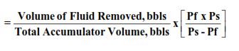
= 20 ÷180 X (2200 x 3000) ÷ (3000-2200)
= 917 psi