Objective
The objectives of this section are to introduce the Fundamental Principles of Well Control.
General Information
The function of Well Control can be conveniently subdivided into three main categories, namely PRIMARY WELL CONTROL, SECONDARY WELL CONTROL, and TERTIARY WELL CONTROL. These categories are briefly described in the following paragraphs.
Primary Well Control
It is the name given to the process which maintains a hydrostatic pressure in the wellbore greater than the pressure of the fluids in the formation being drilled, but less than formation fracture pressure. ( For more info please visit: primary well control and kick prevention)
- If hydrostatic pressure is less than formation pressure then formation fluids will enter the wellbore.
- If the hydrostatic pressure of the fluid in the wellbore exceeds the fracture pressure of the formation then the fluid in the well could be lost.
- In an extreme case of lost circulation the formationpressure may exceed hydrostatic pressure allowing formation fluids to enter into the well.
- An overbalance of hydrostatic pressure over formation pressure is maintained, this excess is generally referred to as a trip margin.
Secondary Well Control
If the pressure of the fluids in the wellbore ( i.e. mud) fails to prevent formation fluids from entering the wellbore, the well will flow. This process is stopped using a “blow out preventer” BOP Stack to prevent the escape of wellbore fluids from the well. This is the initial stage of secondary well control. Containment of unwanted formation fluids.
Tertiary Well Control
Tertiary well control describes the third line of defense. Where the formation cannot be controlled by primary or secondary well control (hydrostatic and equipment). An underground blowout for example. However, in well control, it is not always used as a qualitative term. ‘Unusual well control operations’ listed below are considered under this term:-
- A kick is taken with the kick-off bottom (check also: Kick warning signs, Causes of kick, Kick tolerance).
- The drill pipe plugs off during a kill operation. (check also Wait & weight method, Driller’s method)
- There is no pipe in the hole.
- Hole in drill string.
- Lost circulation.
- Excessive casing pressure.
- Plugged and pipe sticking off the bottom.
- Gas kick percolation without gas expansion.
We could also include operations like stripping operations or snubbing in the hole or drilling relief wells. The point to remember is “what is the well status at shut-in?” ( check also: hard shut in procedure – Soft shut in procedure) This determines the method of well control.
Hydrostatic Pressure
Hydrostatic pressure is defined as the pressure due to the unit weight and vertical height of a column of fluid.
Hydrostatic Pressure = Fluid Density x True Vertical Depth
Pressure Gradient psi/ft = Fluid Density in ppg X 0.052
Hydrostatic Pressure psi = Density in ppg X 0.052 X True Vert. Depth
Formation Pressure
Formation pressure or pore pressure is said to be normal when it is caused solely by the hydrostatic head of the subsurface water contained in the formations and there is pore to pore pressure communication with the atmosphere. Dividing this pressure by the true vertical depth gives an average pressure gradient of the formation fluid, normally between 0.433 psi/ft and 0.465 psi/ft.
Note: The point at which atmospheric contact is established may not necessarily be at sea-level or rig site level.
Normal Formation Pressure
- Normal Formation Pressure is equal to the hydrostatic pressure of water extending from the surface to the subsurface formation.
- Increasing the dissolved solids (higher salt concentration) increases the formation pressure gradient
- Increasing in the level of gases in solution will decrease the pressure gradient.
- Temperature also has an effect as hydrostatic pressure gradients will decrease at higher temperatures due to fluid expansion.
- In the absence of accurate data, 0.465 psi/ft is often taken to be the normal pressure gradient.
Abnormal Pressure
Every pressure which does not conform with the definition given for normal pressure is abnormal. (check also causes of abnormal pressure)
The principal causes of abnormal pressures are:-
Under-compaction in shales
When first deposited, shale has a high porosity. More than 50% of the total volume of uncompacted clay mud may consist of water in which it is laid. During normal compaction, a gradual reduction in porosity accompanied by a loss of formation water occur as the thickness and weight of the overlying sediments increase. Compaction reduces the pore space in shale, as compaction continues water is squeezed out.
Salt Beds
Continuous salt depositions over large areas can cause abnormal pressures. Salt is totally impermeable to fluids and behaves plastically. It deforms and flows by recrystallization. Its properties of pressure transmission are more like fluids than solids, thereby exerting pressures equal to the overburdened load in all directions. The fluids in the underlying formations cannot escape as there is no communication to the surface and thus the formations become over pressured.
Mineralisation
The alteration of sediments and their constituent minerals can result in variations of the total volume of the minerals present. An increase in the volume of these solids will result in increased fluid pressure.
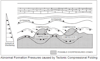
Tectonic Causes
Is a compacting force that is applied horizontally in subsurface formations. In normal pressure environments, water is expelled from clays as they are being compacted with increasing overburden pressures. If however an additional horizontal compacting force squeezes the clays laterally and if fluids are not able to escape at a rate equal to the reduction in pore volume the result will be an increase in pore pressure.
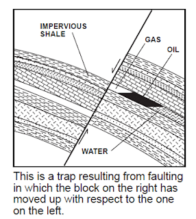
Faulting
Faults may cause abnormally high pressures. Formation slippage may bring a permeable formation laterally against an impermeable formation preventing the flow of fluids. Non-sealing faults may allow fluids to move from a deeper permeable formation to a shallower formation. If the shallower formation is sealed then it will be pressurised from the deeper zone.
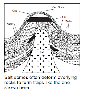
Diapirism
A salt diapirism is an upward intrusion of salt to form a salt dome. This upthrust disturbs the normal layering of sediments and overpressures can occur due to the folding and faulting of the intruded formations
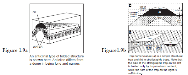
Reservoir Structure
Abnormally high pressures can develop in normally compacted rocks. In a reservoir in which a high relief structure contains oil or gas, an abnormally high-pressure gradient as measured relative to the surface will exist as shown in the following fig:
Formation Fracture Pressure
- If wellbore pressures were to equal or exceed this fracture pressure, the formation would break down as fracture was initiated, followed by loss of mud, loss of hydrostatic pressure and loss of primary control.
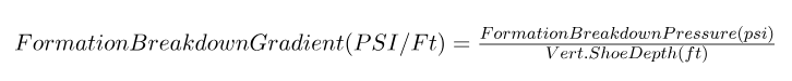
- Fracture pressures are related to the weight of the formation matrix (Rock) and the fluids (water/oil) occupying the pore space within the matrix, above the zone of interest. These two factors combine to produce what is known as the overburden pressure.
- Assuming the average density of a thick sedimentary sequence to be the equivalent of 19.2 ppg then the overburden gradient is given by: 0.052 x 19.2 = 1.0 psi/ft
- Since the degree of compaction of sediments is known to vary with depth the gradient is not constant.
- Onshore, since the sediments tend to be more compacted, the overburden gradient can be taken as being close to 1.0 psi/ft.
- Offshore, however the overburden gradients at shallow depths will be much less than 1.0 psi/ft due to the effect of the depth of seawater and large thicknesses of unconsolidated sediment. This makes surface casing seats in offshore wells much more vulnerable to break down and is the reason why shallow gas kicks should never be shut in.
Leak Off Tests
The leak off test establishes a practical value for the input into fracture pressure predictions and indicates the limit of the amount of pressure that can be applied to the wellbore over the next section of the hole drilled. It provides the basic data needed for further fracture calculations and it also tests the effectiveness of the cement job.
The test is performed by applying an incremental pressure from the surface to the closed wellbore/casing system until it can be seen that fluid is being injected into the formation. Leak-off tests should normally be taken to this leak-off pressure unless it exceeds the pressure to which the casing was tested. In some instances as when drilling development wells this might not be necessary and a formation competency test, where the pressure is only increased to a predetermined limit, might be all that is required.
1.7.1 Leak-Off Test Procedure
1.7.2 Formation Breakdown Pressure (psi) = hydrostatic pressure of mud in casing + applied surface pressure
The formation breakdown pressure can be expressed as a GRADIENT.
The formation breakdown gradient expressed as a maximum allowable mud weight:

Maximum Allowable Annular Surface Pressure
MAASP is the maximum surface pressure that can be tolerated before the formation at the shoe fractures.
MAASP = (Fracture gradient – Mud gradient) x True Vert. Shoe Depth
or as:
MAASP = (Max equiv. mud wt. – Mud wt. in casing) x (0.052 x True Vert. shoe depth)
MAASP is only valid if the casing is full of the original mud, if the mud weight in the casing is changed MAASP must be recalculated. The calculated MAASP is no longer valid if influx fluids enter into the casing.
Casing Setting Depths
The choice of casing setting depths for all the types of casing strings is a vital part of the well planning process. An incorrect decision with the casing setting depths too shallow could have serious consequences. An unnecessarily deep setting depth could have adverse economic consequences when considering the extra time needed to drill the hole deeper and the extra amount of casing required to be run and cemented. ( check also: casing running procedures)
Deep Casing Setting Depths
The selection of deeper casing setting depths will use different criteria to those used for shallow casing seats.
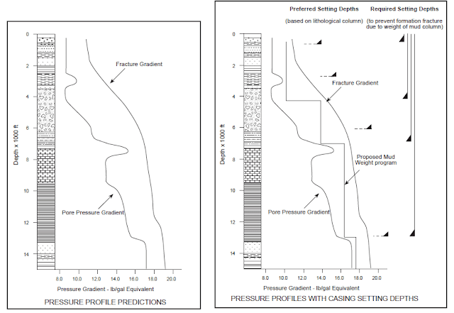
Initial selection of the setting depth is made with reference to the anticipated lithological column, formation pressure and fracture gradient profiles.
Once all the information has been collated from offset well data a plot similar to that shown in Fig 1.16 can be drawn up. By studying the geology and pressure profiles, tentative setting depths can be chosen based on the prevention of formation breakdown by mud weights in use in the subsequent hole section.
See Fig 1.17. From a Well Control point of view, it is necessary to determine whether this tentative setting depth will give adequate protection against formation breakdown when a kick is taken. A kick tolerance “factor” will normally be applied.
Circulating Pump Pressure
The pressure provided by the rig mud pump is the sum of all of the individual pressures in the circulating systems. All the pressure produced by the pump is expended in this process, overcoming friction losses between the mud and whatever it is in contact with:
- Pressure loss in surface lines
- Pressure loss in drill-string
- Pressure loss across bit jets
- Pressure loss in annulus
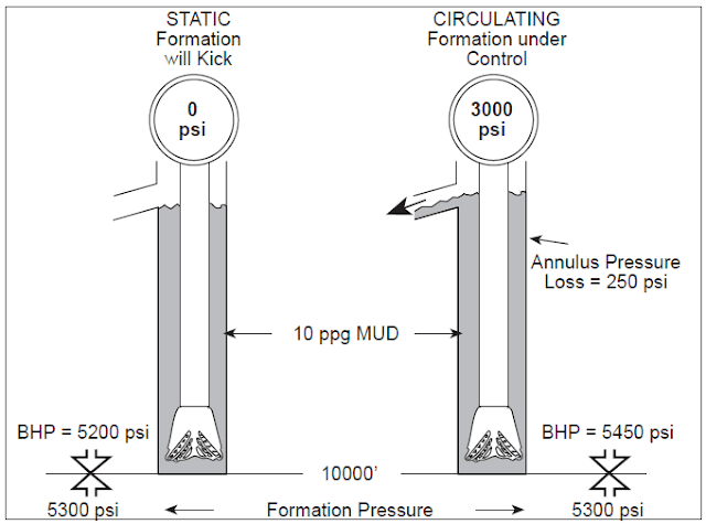
Pressure losses are independent of hydrostatic and imposed pressures (check also: Pressure Loss Calculations). Pressure losses in the annulus act as a “backpressure” on the exposed formations, consequently the total pressure at the bottom of the annulus is higher with the pump on than with the pump off.
Circulating bottom hole pressure = Static bottom hole pressure + Annulus pressure losses
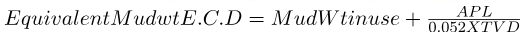
Check also (Equivalent Circulating Mud article)
Where:
APL in drilling = Annulus Pressure Loss
Where:-
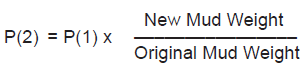
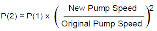
P(1) = Original pump pressure at original pump speed.
P(2) = New circulating pressure at new pump speed.