The main application of balanced Cement plugs is to secure a well and cure mud losses, prior to a side track or in the course of Well Abandonment. The spotting of the plugs inside the casing (Check our guide for Casing Design Calculations Steps) or in the open hole will be through drill pipe with a ‘cement stinger‘ (smaller bore pipe) extension. And of course, the usage of casing preflushes, spacers, and wiper plugs is useful to reduce contamination with drilling fluid in the hole or (inside drill pipe). In this article, we shall discuss the balanced cement plug applications, design considerations, techniques, procedures, calculations, also you can download our excel sheet. (check also cement design guidelines)
What Is The Main Balanced Cement Plug Application?
Usually, in the oil, gas, or water well, a plug may be required. However, this balanced plug is a relatively small volume of cement slurry, but we always use it in the wellbore for various purposes:
- to sidetrack above a fish (check also: sidetracking well) (a lost tool in hole)
- For initiating directional drilling (a drilling whipstock)
- to plug back a depleted zone or a well (well abandonment)
- For solving a Mud Loss / lost circulation problem during drilling
- to test anchor.
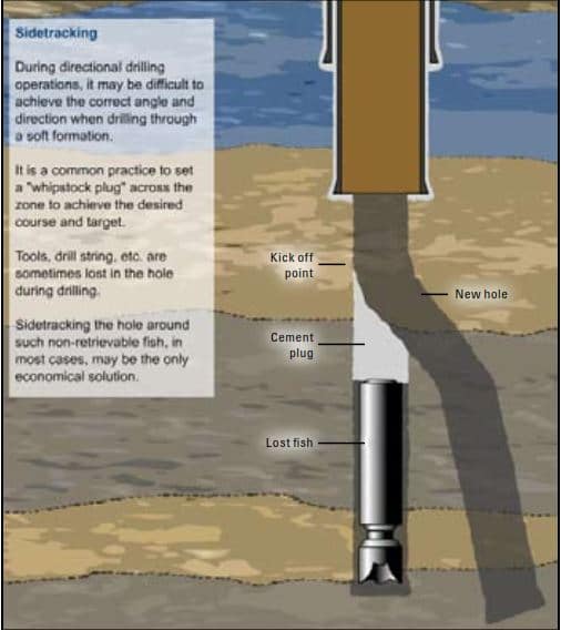
Sidetracking and directional drilling
During directional drilling operations, it may be difficult to achieve the correct angle and direction when drilling through a soft formation. So, it is common practice to set a whipstock plug across the zone to achieve the desired course and target. Also, After losing tools, drill string (Check also drill string design), etc., in the hole during drilling, sidetracking the hole around, such non-retrievable fish may be the only solution (Fig.1)
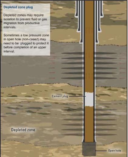
Plugback of a depleted zone
Surely Depleted zones may require isolation to prevent the possible migration of fluid and/or gas from productive intervals. Also, Isolation may also be important to protect a low-pressure zone in an open hole before the completion of an upper interval (Fig.2).
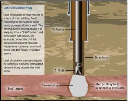
Lost circulation
Setting properly formulated slurry across the thief zone can stop and cure the Mud loss / Circulation Lost. Although the cement slurry may be lost to the thief zone, it will harden and consolidate the thief or weak formation.
A balanced cement plug can also be set on top of a zone to isolate it or keep it from being fractured under the hydrostatic pressure that might be developed during the cementing of a casing string (plugback before a casing job).
Usually, lost-circulation Material/additives (advanced fiber technology to control losses) are included in such cement plugs to ensure a successful job (Fig. 3).
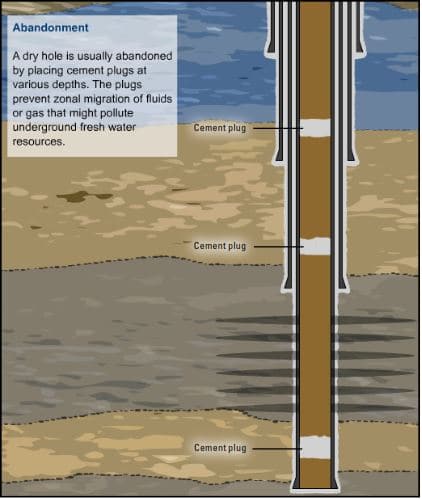
Abandonment
A dry hole is usually abandoned (Fig. 4) by setting balanced cement plugs at various depths to prevent zonal communication or any migration of fluids and/or gas that might pollute underground freshwater sources. Depleted zones or formations are plugged when they are abandoned (Well Abandonment).
In most countries today, oil and gas well operators and service companies must carefully follow abandonment procedures, which are dictated by governmental authorities. The United States regulates almost every phase of a well, and the requirements vary from state to state. Personnel should learn the government regulations concerning cementing in the country or region where the specific job is to be performed.
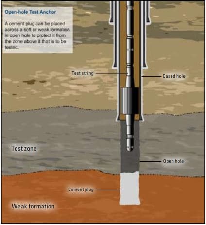
Test Anchor
When a soft or weak formation exists in an open hole below a zone to be tested and it is impractical or impossible to place a sidewall anchor or bridge plug, a test anchor (Fig. 5) may be used to provide the necessary support.
Balanced Cement Plug slurry Design
The design of the slurry varies according to the specific purpose of the plug and requirements common to all, such as durability, good bonding characteristics, and resistance to contamination. Plugs must also be able to carry the weight of the drill pipe during testing for soundness, often practiced in abandonment operations as required by local regulations.
Abandonment and lost circulation plugs are designed for minimal contamination with hole/casing fluid content to ensure good bonding and sealing against fluid movement. Strength is not a major criterion. Lost circulation plugs require design for the lowest practical density and early development of reasonably minimum strength.
Kick-off plugs need to be designed to develop a hardness higher than the formation to be drilled, as early as possible. Formulating a denser slurry by reducing the water/cement ratio will meet both objectives. The denser and more viscous slurry is also less susceptible to mud contamination.
Balanced Cement Plug Job design Considerations
The design of a job starts with the definition of the objective. Setting a plug for lost circulation is quite different from setting a plug to abandon a depleted zone or plug back a well. The design parameters to be considered are as following:
- Cement volume
- The Properties of Cement
- Cement plugback
- Reverse circulation
- Plug placement tools and drill pipe balls and darts are used.
Cement volume
The length and depth of abandonment of balanced cement plugs are normally stated by government regulations.
Whipstock plugs must be long enough to provide for a gradual deviation of the bit (Check Also: Drilling Bits Types Used In Oil & Gas Wells). If the exact depth for a balanced whipstock plug is needed, cement excess and reversing might be necessary.
CMT Properties
Cement slurries must be tested in the laboratory before use in the field. The testing parameters are slightly different from those used for primary casing cementing jobs ( Check Our Guide to Get A Successful Primary Casing Cementing), and the test design must consider the different bottom hole temperatures and placement times and whether the slurry is to be batch mixed or not
Cement Slurry densities usually range from 15.6 ppg to 17.5 ppg to ensure good cement compressive strength development. Lighter slurries are usually used for lost circulation control to avoid the loss of the circulation or cement into the formation. Special cement slurries can also be used in certain cases.
For sidetracking purposes, the ideal is to have set cement with a compressive strength higher than that of the formation. This can often be achieved by having a reduced-water or higher-density slurry. Reduced-water slurries (± 17.5 ppg) will develop compressive strengths of ± 8,500 psi, compared with ± 5,000 psi for a normal 15.8 ppg slurry. The addition of sand or any other weighting agent will not improve the compressive strength of a lower-water-content slurry.
Two important cement properties are rheology and cement thickening time/waiting on cement (WOC) time.
- Rheology: Viscous slurries with high drilling fluid gel strength are needed for lost circulation plugs to restrict flow into voids or fractures. When the cement is placed via coiled tubing, the slurry rheology needs to be designed with low viscosity to avoid high friction pressures during placement.
- Thickening time and waiting on cement time: A minimum of 500 psi in compressive strength is normally recommended for drilling-out cement. Rig time can be saved with the proper slurry design. Early compressive strength depends heavily on thickening time. Slurries must be designed for a thickening time according to well conditions and job procedures, plus reasonable safety.
Cement plugback
As with all cement jobs, the objectives of a cement plugback are to place good quality, uncontaminated cement slurry where it is required and to have the slurry develop good quality set cement properties. Several tools can help achieve these objectives.
Diverter tool
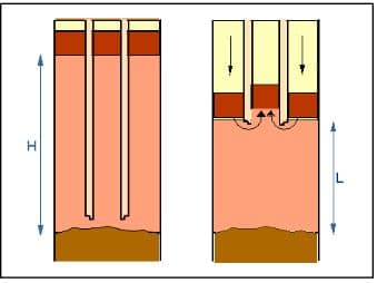
The diverter tool is connected to the end of the drillpipe or tubing through which the balanced cement plug is placed (Fig. 6). The tool contains jets oriented so that the fluids pumped through it are directed upward into the annulus. A downward jetting action may result in CMT contamination or the breaking of any viscous gel pill placed as a base below the CMT plug.
Drill pipe centralizer
The use of a drill pipe centralizer to center the drill pipe and diverter tool will help achieve placement of the cement as designed.
Viscous pill
A viscous pill can be spotted below the bottom of the balanced cement plug before the cementing stage to help provide a base for the heavier slurry in lighter muds and to prevent the CMT from sinking. Figure 7 shows a successful plug job.
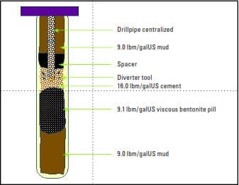
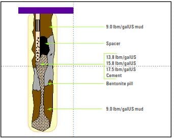
Figure 8 shows the effects of incorrect balanced cement plug placement. No diverter tool is used. The jetting action of the cement coming out of the end of the pipe breaks the viscous pill, allowing the cement slurry to sink down the hole. The drillpipe is not centralized, so the cement channels as it exits the drill pipe.
Reverse circulation
It is common practice to spot extra cement in the hole to ensure the correct top of cement (TOC) in an open hole (especially if the open hole size is unknown).
The drill pipe is run in a hole to the desired top of the cement, and the excess slurry is reverse circulated out. Reverse circulation is preferred over conventional circulation bottoms-up because it is faster and safer. Bottom-up circulation takes longer, and the slurry might set. If it is not completely circulated out, the drill pipe can get stuck.
One important point to consider is fracture pressure safety limits; reverse circulating tends to apply more pressure directly onto the formation than does direction circulation because the friction pressure is at the top and inside the drill pipe in the second case (Fig. 9).
The slurry thickening time should take into account this reverse circulating time
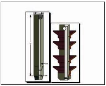
Plug placement tool
The plug placement tool consists of a landing sub (Drilling Subs) at the end of the drill pipe (above the diverter tool). A locator sub set at a calculated distance above the landing sub (Fig. 10). The depth of the locator sub depends on the length of the balanced cement plug and hole or D/Ps dimensions. Darts with a burst disc are used before and behind the cement slurry. When they land in the locator sub, the burst discs rupture, indicating slurry placement. The darts must be dropped from a plug launcher at the surface.
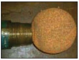
Drill pipe balls and darts
Drill pipe darts (with rubber fins), sponges, or rubber balls can be pumped ahead of the cement slurry to clean the inner diameter of the drill pipe and indicate balanced plug placement. A sponge ball exiting the end of the drill pipe is shown in Figure 11. Rubber darts or balls are more effective than the sponge balls.
Balanced Cement Plug Placement Techniques
Before starting discussing the Plug Procedure, you should know that there are three methods to place a plug at the desired location:
- Using Dump Bailer
- Balanced Plug Method
- Two Plug Technique
Cement Plug By Dump Bailer Definition & Procedure
By dump-bailer under low-pressure conditions, in cased holes. The bailer is run on a wire-line, containing a low gel cement slurry. At the desired depth the bailer is opened and the cement dumped onto a ‘bridge’, formed by sand/gravel or a permanent plug.
Balanced Cement Plug Definition & Procedure
The balanced plug method is based on pumping preflush, cement slurry, and spacer (in that order) into a D/P with a stinger attachment positioned at the desired plug setting depth. The fluid train is displaced with mud until the hydrostatic pressure inside the pipe or stinger equals that in the annulus. This requires the hydrostatic pressures of pre-flush and spacer columns to balance. When hydrostatic pressures balance the pipe is pulled, leaving the balanced plug in place.
Two (Bottom & Top) Plug Technique
The two plug technique for placing plugs at greater depth, in situations where precise calculation of cement volumes is impossible or for small cement volumes. The method uses bottom and top wiper plugs inside an open-ended drill pipe fitted with a catcher for the top plug. The cement is contained between the plugs, which ensures minimum contamination and being displaced with mud. The pipe is pulled back when the top plug seats. The plug is dressed off at the desired depth and excess cement is (reverse) circulated out.
Balanced Cement Plug Job Procedure
To perform a balanced cement plug job, follow this procedure:
- Firstly, Run D/P or tubing with a diverter sub to the depth at which the bottom of a CMT plug is required. Then, circulate to condition the hole and mud and to make sure the bottom hole temperature stated in the job design is the actual bottom hole temperature.
- Secondly, Pressure test the treating lines.
- Thirdly, Pump spacer or wash ahead of the cement slurry.
- Fourthly, Mix and pump the cement slurry. If the slurry volume permits, use batch mixing.
- Fifthly, Pump spacer or wash behind the cement slurry. Also, The volume should be calculated to balance the cement plug.
- Sixthly, Displace the calculated amount of displacing fluid. And under-displace by 1/2 bbl to 1 bbl for safety.
- Seventhly, Open the return lines to the displacement tank on the unit, and allow the plug to balance itself either by return flow or by vacuum.
- Eighthly, Pull the drillpipe up above the top of the cement. (Observe whether flowback occurs when the drillpipe joints are broken.)
- Ninthly, Reverse circulate if conditions allow to clean the hole. Also, observe the returns for spacer, wash, or cement.
- The last step of CMT plug procedure is to pull out of the hole and WOC.
Balanced Cement Plug Job Calculation
Of course, before performing the above plug procedure, you should perform its calculation. This Calculation is so simple as you will have to calculate the following:
- The balanced cement plug slurry volume calculation
- The heights of the plug and pre-flush with the drillpipe in place calculation (required to calculate the displacement volume)
- Also, The required displacement volume to balance.
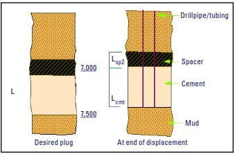
Calculate The Volume Of Cement (Vcmt ):
Vcmt = L × CH × excess factor
Where:
- L = Length of column of cement in open hole
- CH = capacity of open-hole from standard tables ( ft3/ ft)
- Excess Factor = 20%
Calculate The Length Of Balanced Plug With Work String In Place (Lcmt )
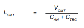
Where:
- CAN = capacity of the annulus between drill pipe or tubing and open hole (ft3/ft)
- CTBG = capacity of tubing or drill pipe (ft3 /ft)
Calculate the volume of spacer behind the cement (VSP2 )
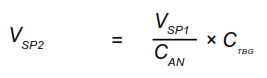
Where:
- VSP1 = Volume of water/spacer that planned to be pumped ahead.
- CAN = capacity of the annulus between drill pipe or tubing and open hole (ft3/ft)
- CTBG = capacity of tubing or drill pipe (ft3/ft)
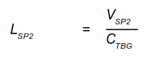
Calculate The Length Of Spacer Behind Cement (LSP2 )
Calculate The Displacement Volume (VD )
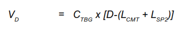
Where:
D = depth of workstring (bottom of balanced cement plug, ft)
Note : The plug is desirable to be under-displaced by 0.5 bbl to 1 bbl.
Download Balanced Cement Plug Calculations Excel Sheet
Download Calculations Excel Sheet Simple Form # 1
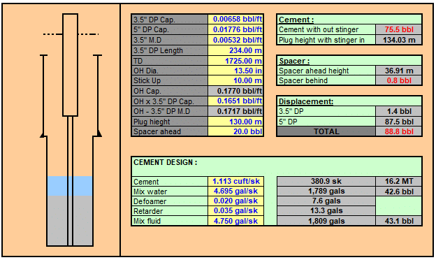
Cement plug calculation excel Download Link # 1
Download Cement Plug Calculations Excel Sheet Advanced Form # 1
Balanced Cement plug calculation excel Download Link # 2
Download Full Casing Cementing Calculation Excel Sheet
You can also download full casing cementing calculations sheet which include plug calculation excel sheet
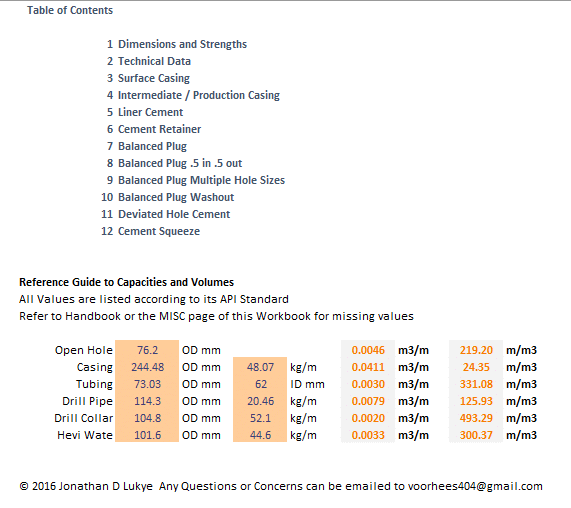
Download Full Casing Cementing Calculations Sheet
I am Darkman 7 years experience