Halliburton’s Geopilot RSS rotary steerable system also uses “point the bit” technology. The design concept involves the deflection of a flexible shaft between the drilling bit and the drill string. A high-side reference housing contains a compact and rugged computer-controlled bias unit (eccentric rings) to impart a controlled deflection to this shaft element, allowing for continuously variable – both in tool face and effective bend angle – steering.
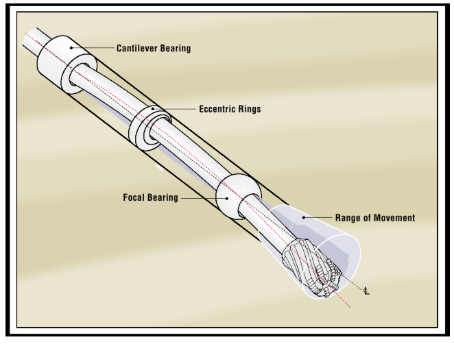
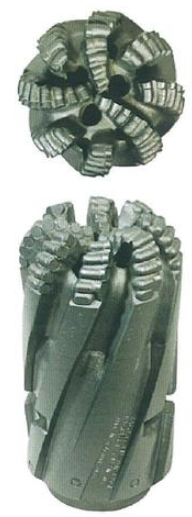
Figure 1 shows the concept. The GeoPilot system is designed for use with extended gauge PDC drill bits which aim to minimize the nonconstructive bit behaviors caused by short gauge bits i.e., hole spiraling. The extended gauge bits used with Halliburton rotary steerable system are box-up bits (see Figure 2) and are usually provided by Halliburton DBS as part of the overall package.
Advantages
The GeoPilot System introduces many advantages over conventional steerable motors. With the ever-increasing complexity of well profiles, some wells are simply not economical or possible to drill with conventional technology.
- The Halliburton GeoPilot is a rotary steerable tool. As such, it is not dependent upon sliding to produce a deviated hole. We can achieve the steering more effectively in extended reach and horizontal applications where weight transfer to the bit is problematic.
- As the drill pipe rotates while steering and drilling straight, hole cleaning will improve. ECD will be kept consistent rather than fluctuating as the hole is loaded with cuttings while sliding. Then cuttings beds are agitated and unloaded while rotating.
- Hole quality using the extended gauge bits matched to the GeoPilot is much improved, with lower micro tortuosity, lower friction factors, easier casing runs, and a more significant maximum collar pass-through diameter. Halliburton GeoPilot RSSis the only commercial rotary Steerable tool using extended gauge bits.
- Higher string rpm can be used, as there is no bend in the mud motor to limit rpm.
- Downhole vibration is reduced using extended gauge bit technology, increasing the reliability of the MWD tools and the Halliburton GeoPilot RSS.
- It is possible to steer the well with much more control due to accurate near-bit measurements and features such as cruise control. Continuous profiles are possible.
- The GeoPilot direction can be remotely programmed or manually controlled. Using an INSITE surface control unit, the GeoPilot’s direction can be changed in minutes.
- Eliminating the time spent to orient the tool face before conventional sliding.
How The GeoPilot Steers
The Halliburton rotary steerable system is designed to bend a shaft to point the bit where the hole should be steered. The bendable shaft runs inside a slowly-rotating control housing. A reference stabilizer with friction carriages prevents the control housing from freely rotating with the drill string and provides a stable reference from which the tool can work.
The heart of the tool is the bias unit that resides inside the lower part of the housing. The bias unit comprises two eccentric rings that bend the shaft that runs through the tool. An upper cantilever bearing and a lower focal bearing support the shaft section that runs through the bias unit. When the shaft is bent, the cantilever bearing acts as a fixed point, not allowing the shaft to bend above it. The focal bearing allows the bit box on the end of the shaft to be tilted in the opposite direction to the eccentrics. This gives the operator 360° of positional control for the tool face selection. We can attain any bend magnitude from zero to full deflection by positioning the eccentric rings appropriately.
How We Could Control Halliburton GeoPilot RSS’ Toolface
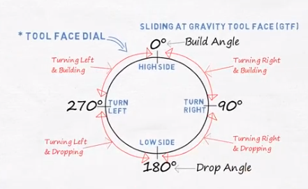
To control the tool face, the Halliburton rotary steerable system utilizes a tri-axial accelerometer stack inside the At-Bit-Inclination (ABI) insert. The ABI tracks the GeoPilot housing tool face relative to the high side of the hole. The downhole software inside the Halliburton RSS monitors the relative position of the housing and the position of the eccentric rings relative to this high side, thus controlling the tool. When the GeoPilot calculates that either the toolface or percentage deflection has drifted out of the target range, the GeoPilot will automatically rotate one or both of the eccentric rings to bring the actual value back into the target range. To maintain the position of the eccentric rings, each eccentric has a home sensor and two quad counters. At the home position, the tool knows the precise location of the eccentric ring relative to the ABI and can re-calibrate its position tracked by the algorithm. The quad counters are used to monitor how far the rings have been moved, and thus the tool can calculate the relative position of the eccentric rings at all times.
The Complete Drilling Package For Halliburton Geopilot
The Halliburton RSS is part of an integrated drilling package consisting of the GeoPilot, a Geo-Span Downlink system, a Sperry-Sun Measurement While Drilling system, INSITE, and an SDBS Extended Gauge Bit. The MWD pulser is used to transmit information back to the surface from the Halliburton rotary steerable system through the standard VDF data lists. MPT negative pulse telemetry or P4M positive pulse telemetry can be used. As a minimum, the MWD tools must contain a DM directional probe, an HCIM, and for operations, using downlink, a PWD sensor. The Geo-Span Downlink system (or Downlink skid) creates a brief negative pressure pulse in the drilling mud without interrupting the drilling process. Advantages of the Geo-Span Downlink System include:
- The signal transmission time is significantly shortened. (Max approx 90 seconds)
- Drilling is not interrupted. – on the fly transmission on the bottom is possible
- Uplink communication is not interrupted. – no gaps in the real-time logs
Approximately 15 percent of the drilling fluids pass through the Geo-Span Downlink skid. A brief pressure drop in the downstream drill fluid is generated by controlling a valve. The pressure drop generates a low-frequency pulse transmitted through the drilling fluid and detected by the PWD bore pressure transducer. The pulses encode signals using pulse position modulation. Integral to the system’s performance is also an extended gauge bit, either PDC or TriCone Bit. If a roller cone bit is used, a sleeve must be used to convert the bit to give an equivalent long gauge performance. Halliburton’s point-the-bit RSS concept will not work with a short gauge bit.
GeoPilot RSS Family

There are many models in that RSS family, which are:
- Geo-Pilot Dirigo Rotary Steerable System: We can achieve accurate well placement with build rates up to 10°/100 feet in larger borehole sizes and up to 15°/100 feet in smaller borehole sizes
- Geo-Pilot® Duro: Lower stabilizer with larger flow area, Strong, self-cleaning reference stabilizer, New driver drilling sub for higher overload protection, Enhanced RPM, and broader operating range
- Geo-Pilot XL: Torsional efficiency monitor sensor provides early warning of stick-slip; long-gauge bit design handles high-torque and drills steeper angles
You can find their exact specs and datasheets through the Halliburton website.