Packer milling is a way of changing the metal that holds or obstructs a completion. It is not, by itself, evidence that the whole packer has been recovered or that the next assembly can pass. The useful question is more specific: which components must be removed, what will remain connected, and how will the remaining object be controlled? DeGeare’s discussion of stuck packers separates release arrangements, cutting components and retrieving the residual body. Those distinctions should remain visible in the workover decision. [1, printed pp. 111–115; PDF pp. 108–112]
A successful review therefore needs more than the label “permanent” or “retrievable.” It needs the actual packer drawing, the condition of the completion and the objective after recovery. This article develops that review through component accounting and an original dimensional example. It does not provide a milling program, tool settings or a substitute for the equipment supplier’s instructions.
Packer milling, release and retrieval are different outcomes
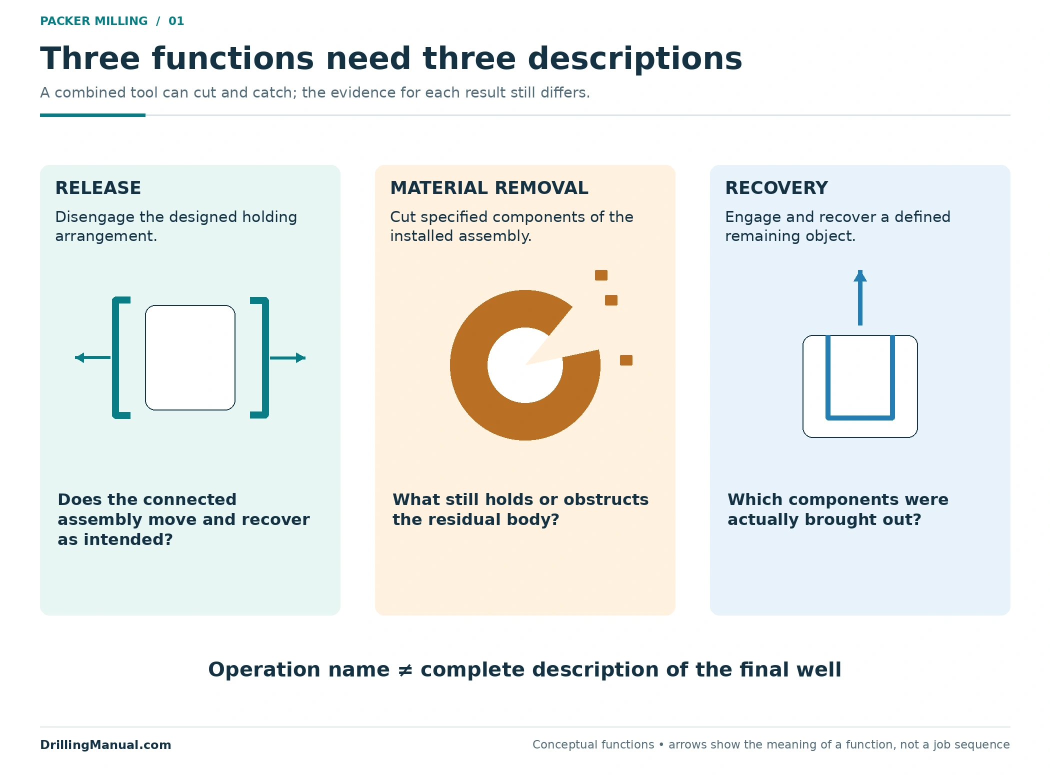
Release concerns the mechanism that normally allows a packer to disengage. Milling removes selected material when that normal route is unavailable or unsuitable. Retrieval concerns engaging and recovering what remains. A tool arrangement can combine cutting and catching functions, but combining them in one assembly does not make the functions identical. The source describes packer mills used with separate retrieving elements and discusses different ways of engaging the residual packer body. [1, printed pp. 111–114; PDF pp. 108–111]
This matters when the job description says only “remove packer.” One interpretation might mean release and recover the intact assembly. Another might mean cut away anchoring components and recover a smaller body. A third might leave material downhole. Those results have different consequences for access and for the next workover objective. The completion drawing should make the intended end state explicit before the selected method is evaluated.
| Function | Question being answered | Question still open |
|---|---|---|
| Release | Has the intended holding mechanism disengaged? | Can the complete connected assembly be recovered? |
| Material removal | Which components have been cut away? | What still holds or obstructs the residual body? |
| Engagement and recovery | What object is caught and brought out? | Does the remaining well configuration meet the next objective? |
Consider two descriptions of the same intended work. “Remove the packer” gives no way to judge whether the residual mandrel is an expected fish or an unexpected obstruction. “Remove specified anchoring components, engage the retained body, and account for the connected lower assembly” makes the assumptions visible. It still is not an operating procedure, but it gives the equipment review a defined object and a defined result. The distinction becomes especially useful when the selected approach changes because the installed assembly differs from the original record.
The general workover operations guide places these activities within the broader intervention. Here the focus is the packer and its connected hardware, rather than rig selection or a complete workover sequence.

Start with the actual equipment, not a family name
DeGeare recommends establishing the manufacturer, model, principal dimensions and setting and release arrangements. The drawing is especially useful when recovered pieces must be compared with the original assembly. An equipment family name may conceal design changes, extensions or a configuration that differs from the one remembered by the crew. Supplier documentation and the installed completion record are therefore part of understanding the fish. [1, printed p. 111; PDF p. 108]
A retrievable packer has a designed release route; that does not guarantee the route will work in its present condition. The book discusses friction, debris and stuck connected tubing among the complications. Conversely, calling equipment permanent does not mean every part must be ground into fragments. The recovery concept may remove the outer holding components while preserving an inner body for engagement. [1, printed pp. 111–113; PDF pp. 108–110]
The distinction between a stuck packer and a stuck string is particularly important. If material around the tubing contributes to the restriction, the condition is not fully described by the packer model. The source treats washing around a fish and cutting packer components as related but different tasks. A review that jumps directly from “cannot pull” to a particular cutter can overlook what is actually resisting movement. [1, printed pp. 111–112; PDF pp. 108–109]
Before packer milling, tie the drawing to the installed configuration. A bare packer illustration is incomplete when a seal-bore extension, blast joint or lower tubing remains attached. Those components can change the length, engagement options and geometry of the object that must eventually be handled. [1, printed pp. 111, 113; PDF pp. 108, 110]
What does packer milling remove, and what remains?
In the permanent-packer arrangement described by DeGeare, the slips and sealing section surround an inner body. A cutover concept can remove outer components without intentionally cutting the mandrel. That separation is the reason a milling shoe and a retrieving element can have different jobs within the same proposed assembly. The required cutting envelope depends on the actual packer and the position of the cutter relative to its parts. [1, printed pp. 113–115; PDF pp. 110–112]
Do not translate “the upper slips were removed” into “the packer is free.” The book specifically discusses the possibility that lower slips remain an impediment after work on the upper section. The drawing below deliberately retains the lower anchoring components after a partial cut. It is a component-state comparison, not a depiction of an approved sequence or a promise that a particular packer behaves this way. [1, printed p. 113; PDF p. 110]
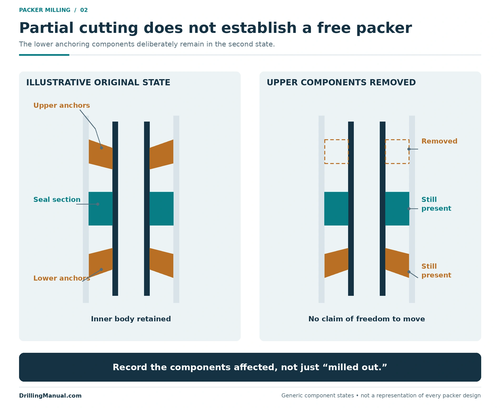
In packer milling reports, the familiar description “mill out” needs qualification. It can hide the difference between removing an obstruction and reducing an assembly to a recoverable fish. Name the components affected and preserve uncertainty where recovery evidence is incomplete. The existing permanent packer guide explains the component families; the workover review must identify which of those components are actually present.
The drawing should also separate what is known from what is inferred. A recovered piece that matches one upper component does not identify the condition of a lower component. A dimension copied from a similar model does not establish the installed model’s geometry. These are different evidence gaps, and they lead to different follow-up questions. Keeping them explicit avoids presenting an assumed component state as an observed result. DeGeare’s emphasis on the actual drawing and on recognizing recovered parts is the basis for this distinction. [1, printed p. 111; PDF p. 108]
A useful sketch distinguishes the original assembly, the intended cut region, the body retained for engagement and any connected equipment below. If one of those cannot be identified, the uncertainty belongs in the recovery assessment. It should not disappear behind a single completion status such as “packer milled.”
Packer milling must account for the remaining fish
Once selected holding components have been removed, something may still need to be caught. The source describes retrieving arrangements that engage beneath the packer and alternatives that engage a suitable internal bore. Their applicability depends on the packer geometry, extensions and equipment attached below. Access to the required engagement location is therefore part of the recovery concept, not a detail to resolve after cutting. [1, printed pp. 113–114; PDF pp. 110–111]
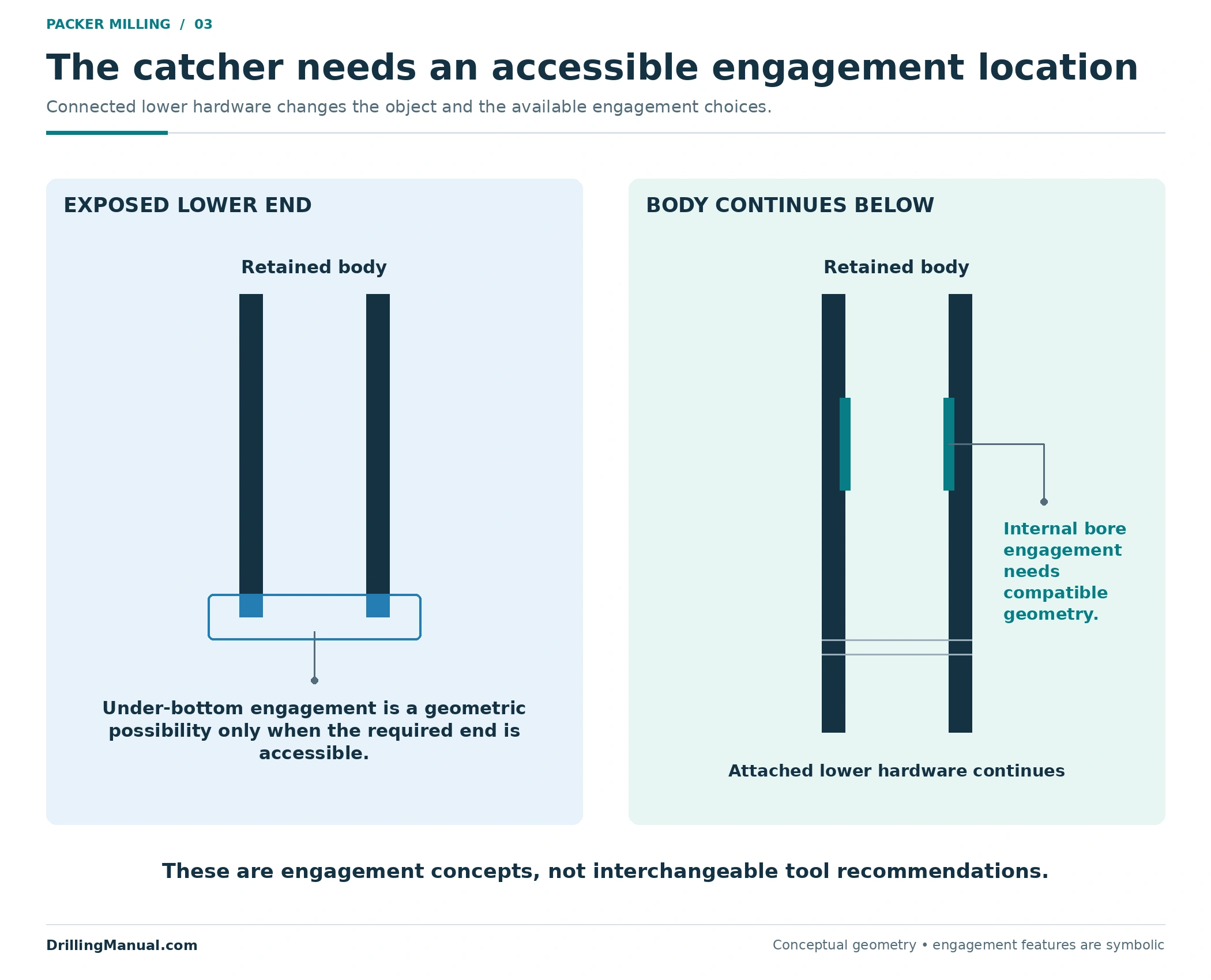
An attached lower string changes the question. It may prevent an assumed under-bottom engagement from being available, and it remains part of the object unless it has been separated by a defined operation. An internal engagement approach also requires an appropriate internal profile and compatible equipment. Neither sketch is a universal recommendation. It illustrates why the catcher cannot be selected from the outer packer diameter alone. [1, printed p. 113; PDF p. 110]
The fishing operations guide covers the broader recovery problem, while the spear fishing tool overview explains one family of internal engagement tools. A family description is background information. The actual catching, holding and release functions still have to match the residual fish described in this job.
Planning packer milling also requires a defined recovery object. “The packer” might refer to the mandrel alone, the mandrel with its extension, or a longer connected assembly. Recording the expected components before the job allows a later comparison with what is recovered. It makes an unexpected missing piece or an additional attached section visible rather than treating either as an accounting detail.
Packer milling has an inner and an outer boundary
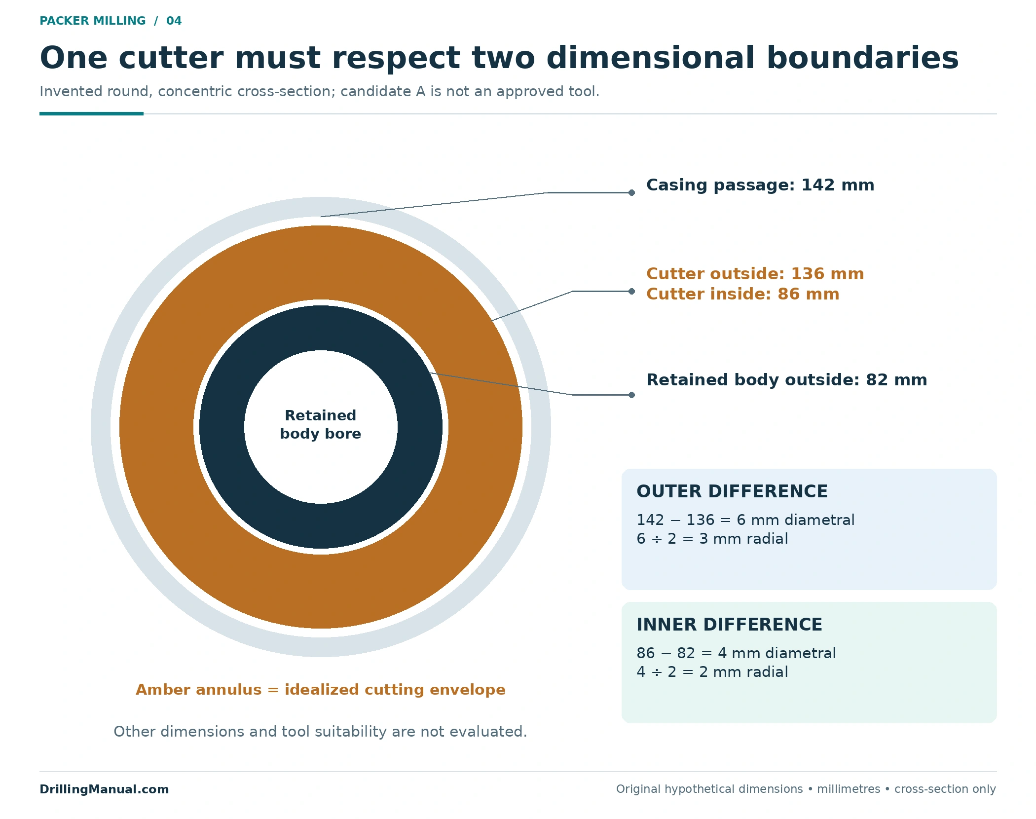
A cutover assembly must fit inside the available casing passage while its internal opening accommodates the body intended to remain. DeGeare relates the shoe geometry to casing drift and mandrel dimensions. This creates two separate checks: the outside must not conflict with the surrounding passage, and the inside must not unintentionally intersect the retained body. Neither check establishes that the cutter reaches every target component. [1, printed pp. 113, 115; PDF pp. 110, 112]
The following numbers are invented for explanation. Assume a round, concentric, static cross-section with a 142 mm casing drift diameter and an 82 mm mandrel outside diameter. Candidate A has a 136 mm outside diameter and an 86 mm inside diameter. Its outer diametral difference is 142 − 136 = 6 mm, or 3 mm radially. Its inner diametral difference is 86 − 82 = 4 mm, or 2 mm radially.
| Hypothetical candidate | Outside / inside diameter | Outer diametral difference | Inner diametral difference | Limited conclusion |
|---|---|---|---|---|
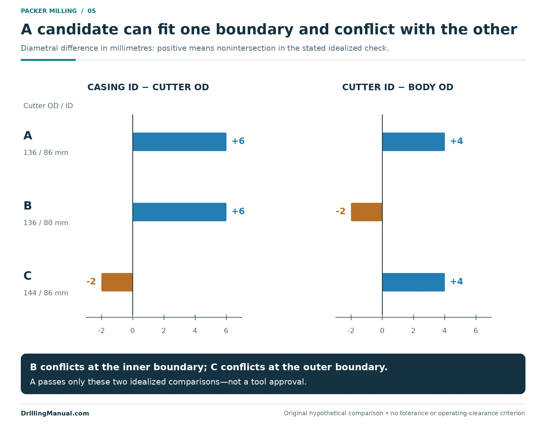
| A | 136 / 86 mm | +6 mm | +4 mm | No intersection in the two stated idealized checks |
| B | 136 / 80 mm | +6 mm | −2 mm | Inner opening conflicts with the 82 mm retained body |
| C | 144 / 86 mm | −2 mm | +4 mm | Outer diameter conflicts with the 142 mm passage |
For packer milling, these positive differences are not approved working clearances. This example omits tolerances, eccentricity, deformation, other restrictions and the actual cutting profile. It also says nothing about strength, debris handling or the suitability of a particular retrieving assembly. Its purpose is to prevent one acceptable diameter from concealing a conflict at the other boundary.
Check axial coverage as a separate question
The cross-section does not resolve the length question. In packer milling, the cutter’s axial position must be understood relative to the components it is intended to remove, while the assembly length must accommodate the relevant packer and extensions. DeGeare discusses both the required length and the relationship between the milling shoe and retrieving arrangement. A candidate can satisfy the two illustrated diameter comparisons yet still fail to represent the required axial geometry. [1, printed pp. 113–115; PDF pp. 110–112]
For review, distinguish the length of the packer body from the length of the complete connected fish. Also distinguish the cutter’s reach from the location where the retriever engages. These dimensions describe different features. A drawing that shows only the tool outside diameter cannot answer them. Marking the intended cutting region and engagement location on the installed assembly makes the assumptions visible, without turning the drawing into an operating sequence or prescribing how much material to remove.
The general milling in drilling operations article covers wider applications. The specific contribution here is the relationship between the casing passage, cutter and retained packer body. An equipment review needs all three, with the dimensions referenced to the actual installed hardware.
Separate recovered debris from recovered equipment
Cutting creates an accounting problem as well as a dimensional one. The source notes that large pieces can be encountered again during milling and can damage the shoe. Seeing metal at surface therefore answers only part of the question. It does not identify all material still around the fish or prove that every holding component has been removed. [1, printed p. 113; PDF p. 110]

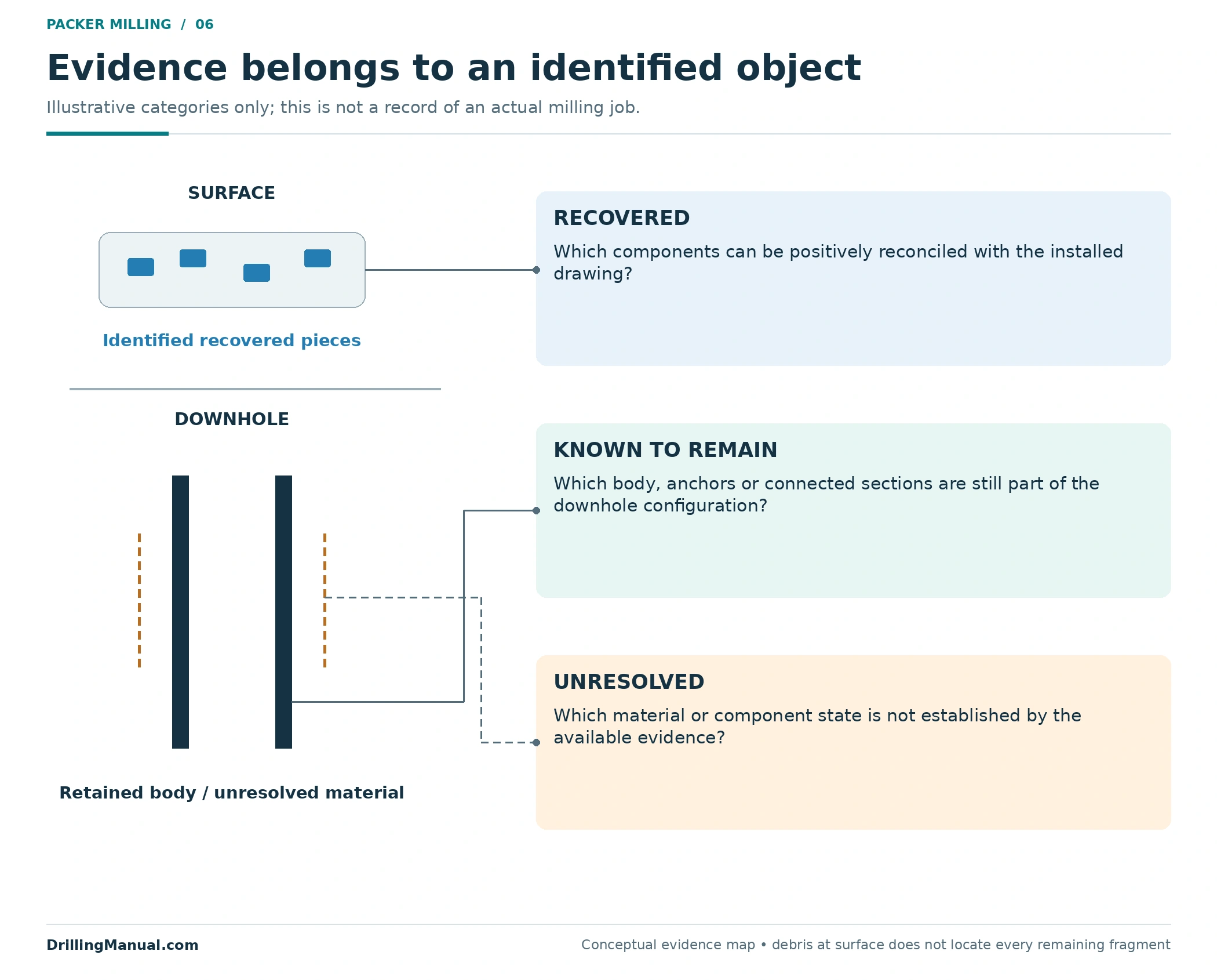
For packer milling, keep three categories distinct: material positively recovered, material known to remain and material whose location or condition is unresolved. Compare identifiable pieces with the equipment drawing where possible. Do not convert an unrecognized collection of cuttings into a complete parts list. This is an evidence framework, not a method for estimating recovered mass from surface appearance.
| Observation | Supported statement | Unsupported extension |
|---|---|---|
| Identifiable component recovered | That component is at surface | Every component of the original assembly is recovered |
| Cutting debris recovered | Some material has reached surface | No loose material remains near or below the fish |
| Residual body engaged | The stated engagement has been achieved | The complete connected assembly is already recovered |
| Recovered assembly compared with drawing | Listed components can be reconciled | Unexamined well barriers or all future access requirements are verified |
Debris transport, fill removal and surface solids handling are larger subjects. They should have their own engineered assessment rather than being reduced to a generic instruction to increase circulation. Here the important result is a defensible description of the remaining configuration.
What must be true after the packer is recovered?
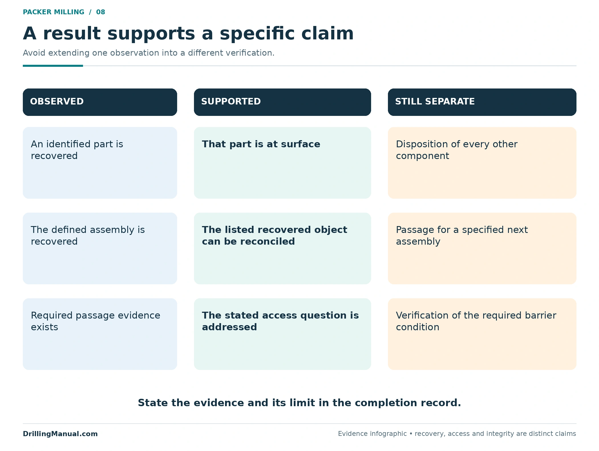
The end point of packer milling should be connected to the next task. Recovering the identified fish, establishing passage for a specified assembly and verifying a required barrier condition are different claims. The book’s emphasis on packer dimensions, connected extensions and catcher selection supports a careful recovery assessment; it does not make recovery evidence a universal test of the rest of the well. [1, printed pp. 111–115; PDF pp. 108–112]
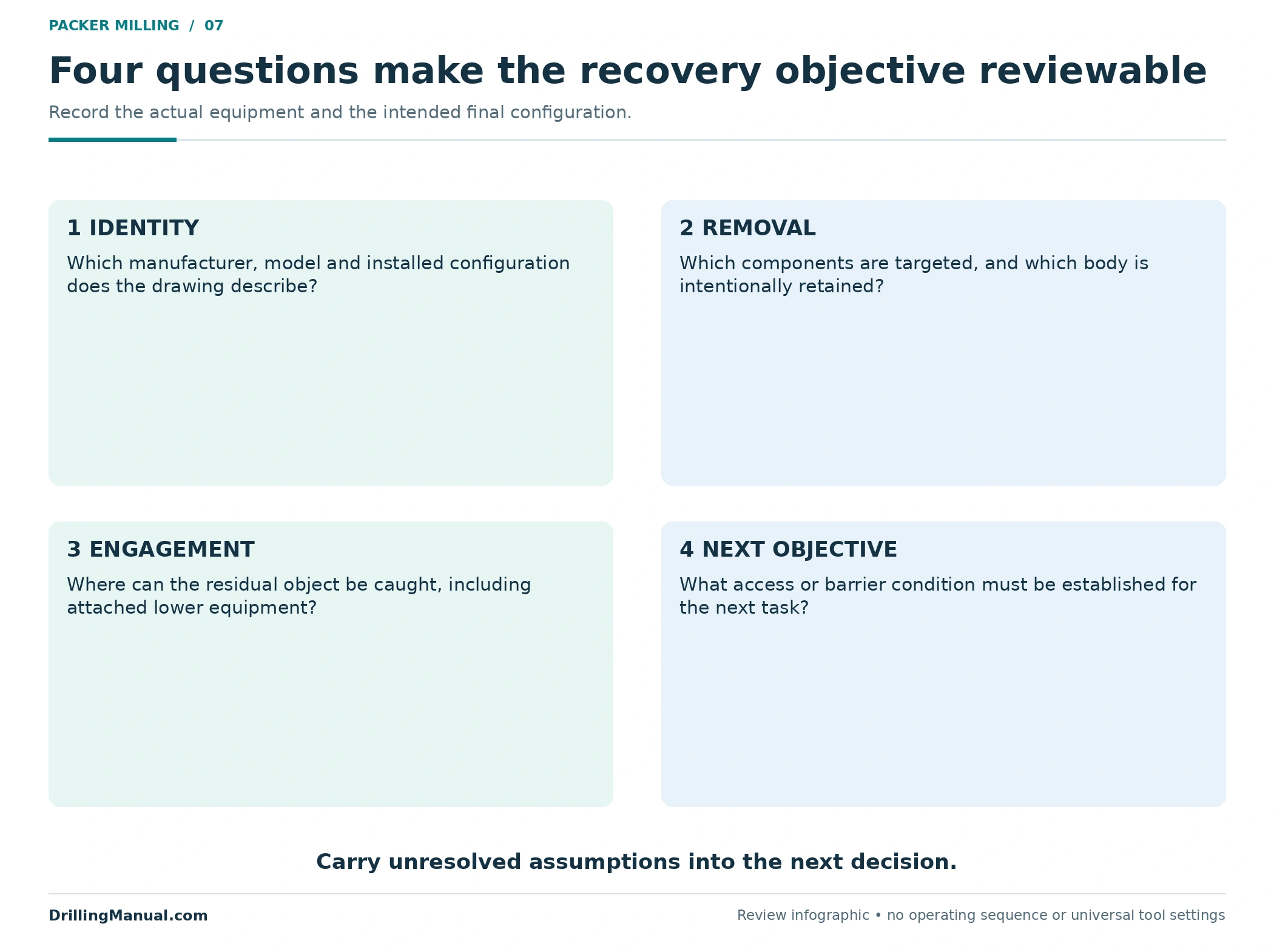
A packer milling review should let another engineer distinguish the intended result from the observed result. State the packer identity, the parts targeted for removal, the body expected to remain, the engagement concept and the route required afterward. Where any of those are uncertain, carry the uncertainty into the next decision. A report that simply repeats the operation name leaves the next team to reconstruct the completion.
| Next objective | Relevant evidence to retain | Do not substitute |
|---|---|---|
| Recover a defined assembly | Recovered components reconciled with the installed drawing | A statement that cutting took place |
| Provide access for a stated tool | Evidence addressing the required passage and remaining restrictions | The nominal casing size alone |
| Establish a required barrier condition | The applicable barrier verification for the revised completion | Recovery of metal at surface |
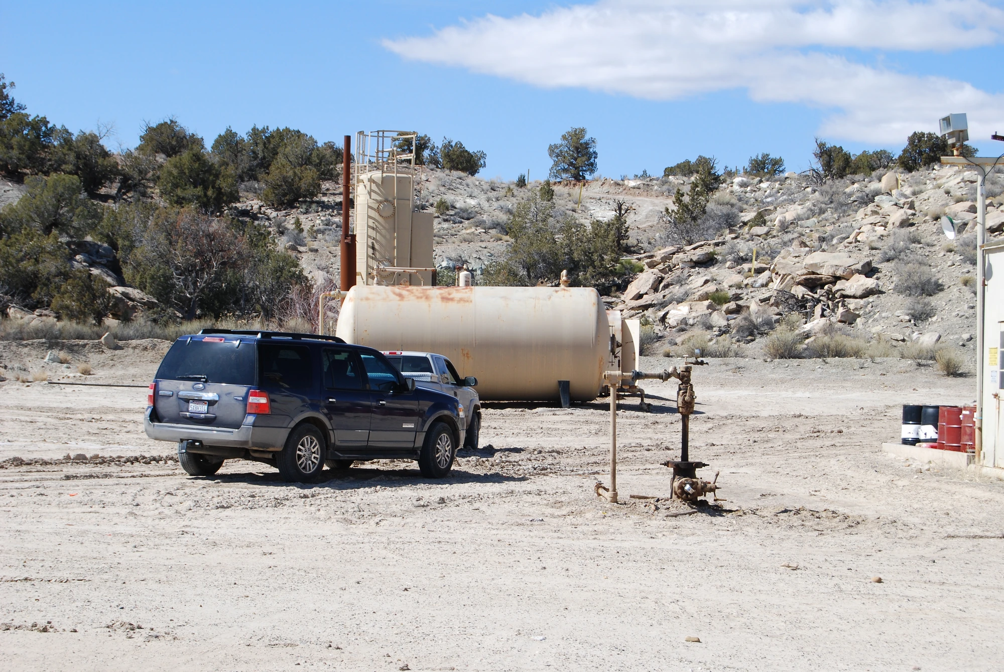

The well integrity guide provides the separate barrier context. A surface wellhead photograph illustrates that context; it cannot show which internal packer components were removed or establish the condition of a downhole barrier.
Frequently asked questions
Can a retrievable packer require packer milling?
Yes. A designed release mechanism does not guarantee successful recovery in the actual downhole condition. DeGeare discusses retained packers, debris and friction as well as difficulties involving connected tubing. The decision still depends on the specific model and cause of resistance. “Retrievable” identifies a design feature; it is not evidence that the installed equipment is free. [1, printed pp. 111–112; PDF pp. 108–109]
Does packer milling remove the entire packer?
Not necessarily. A cutover approach can remove surrounding components while leaving an inner body for engagement and recovery. The work description must state what is cut and what is intended to remain. A residual mandrel or connected extension is still part of the recovery problem until its disposition is established. [1, printed pp. 113–115; PDF pp. 110–112]
Are removed upper slips proof that the packer is free?
No. The source identifies remaining lower slips as a possible impediment after work on the upper section. Partial removal describes a component condition, not the freedom of the complete assembly. The remaining anchoring parts and the connected lower equipment still have to be accounted for. [1, printed p. 113; PDF p. 110]
Does a smaller mill outside diameter establish compatibility?
No. The inside opening also matters when the mandrel is intended to remain. The original example shows a candidate that fits the stated casing passage but intersects the retained body. Even two positive dimensional differences establish only the limited idealized geometry; they do not approve the equipment or its working clearance. [1, printed pp. 113, 115; PDF pp. 110, 112]
Why does equipment below the packer matter?
Extensions and attached tubing can change the length of the fish and whether a proposed engagement location is accessible. A recovery sketch that ends at the packer’s lower edge may therefore omit a decisive part of the installed assembly. The actual drawing and connection record are needed to define what is being recovered. [1, printed pp. 111, 113; PDF pp. 108, 110]
What should the completion record say afterward?
After packer milling, describe the recovered components, the material known to remain and any unresolved uncertainty. Keep that record separate from evidence about tool passage or barrier condition. A precise component record lets the next workover decision start with the revised completion rather than an assumption that the operation name describes everything left downhole.
Technical reference
- Joe DeGeare. The Guide to Oilwell Fishing Operations: Tools, Techniques, and Rules of Thumb, second edition. Gulf Professional Publishing / Elsevier, 2015. Chapter 14, “Retrieving Stuck Packers,” printed pp. 111–115, corresponding to physical PDF pp. 108–112 in the referenced copy. The dimensional example and evidence tables are original teaching constructions, not field dimensions or operating criteria.