Milling is the process of steel removal. Such milling may be mandatory in a lot of cases while drilling oil and gas wells after trials of fishing operations. It will also result in a removal of the steel obstruction in the wellbore and continue drilling to the well target.
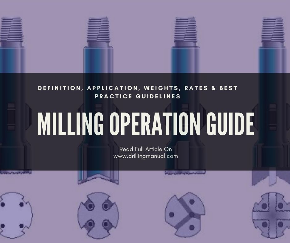
Milling Applications In Drilling:
Milling is not designed only for the fish in the hole (check also fishing operations) but it may be necessary for the following reasons:
- Removal of tools that were previously placed in the well; such as port collars, packer types, bridge plugs, cement shoes, Permanent packers, etc.
- Perform a well sidetrack from the casing by doing a window in the casing then using the whipstock.
- Removal of the left parts of the drill string; such as drilling stabilizers, drilling subs, stabilizer blades, drill pipe, collars etc.
- Milling of drilling tools or other junk in the oil and gas wells; such as drilling bits, hand wrenches, clamps, etc.
- Perform a hole through the collapsed pipe.
- Cut casing liners tops and broken pipes.
- Release special tools such as packer slips.
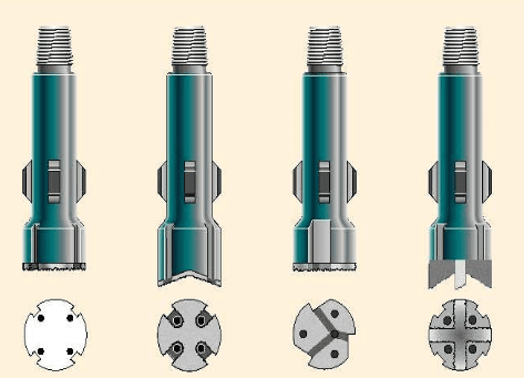
Milling weight
You should mill by torque and not by weight. Most drillers and workover rig operators will run too much weight on rotary shoes, wearing the shoe out prematurely. As long as the shoe is torquing up, you have enough weight on the shoe. If you increase the weight, you will not increase the milling rate and risk wearing out the shoe. The maximum weight to run on a shoe is 1,000 pounds per OD inch of the shoe.
Generally, 3,000 to 4,000 pounds on the shoe is sufficient. The only time you should exceed this maximum weight is when space rings or other parts of a packer begin to turn freely with the shoe. This condition is indicated by a lack of torque in the string. In this case, dry drill with maximum drill collar weight until the fish locks up and begins to torque again.
Milling rates In Drilling Oil & Gas Wells
The milling rate for carbide is listed in surface feet per minute (SFPM) as recommended by the manufacturer. The following table provides the optimum milling rates for several types of mills and shoes:
| Mill or Shoe | Optimum Milling Rate (SFPM) |
|---|---|
| crushed carbide dressed mills | 150 to 200 |
| carbide insert type mills | 150 to 300 |
| crushed carbide rotary shoes | 150 to 200 |
| carbide insert type rotary shoes | 150 to 200 |
Below is the expected milling rate:
| Material | Junk Mill (ft/hr) | Pilot Mill (ft/hr) | Flat Mill (ft/hr) | Washover Shoe (ft/hr) |
| Drillpipe | 2.0 – 6.0 | 2.0 – 4.0 | – | 6.0 |
| Drill Collars | 1.0 – 2.0 | 1.0 – 2.0 | – | 4.0 – 10.0 |
| Packers | 4.0 | – | 2.0 – 3.0 | – |
| Bit cones etc. | 2.0 – 4.0 | – | – | – |
| General junk | 3.0 – 5.0 | – | 2.0 – 4.0 | – |
| Washover pipe/string | 2.0 – 4.0 | 4.0 – 10.0 | – | – |
| Casing | 2 – 4 | 4.0 – 10.0 | – | – |
Converting SFPM to RPM
Because there is not an SFPM indicator on the rig, you must convert the manufacturer’s listed milling rate to revolutions per minute (RPM). Use the following formula to convert SFPM to RPM:
SFPM = mill diameter x RPM x 0.262
The rpm may be derived from the SFPM by multiplying the mill diameter by the milling RPM (check also: Drilling Parameters Optimization In Oil & Gas). This result is then multiplied by a constant, 0.262. For example, a certain mill’s diameter is 4.5″ and the milling rate in RPM is 120. You would calculate the SFPM in this way: 4.5 x 120 x 0.262 = 142 SFPM.
With clear water workover fluids, try to get the annular velocity up to 120 ft/min. Pumping high viscosity pills aids in lifting the cuttings to the surface. Check the cuttings coming over the shaker screen to determine how the milling is progressing.
Note: Milling torque will cause 8 round tubing to make up at least 1″ per 1,000 ft. of depth.
Milling Guidelines:
- Keep mud yield point is high enough prior to milling operations
- Start rotation before the top of fish with a minimum of 3 ft.
- Adjust WOB & RPM (start with 70 rpm and monitor the torque while increasing RPM ) as you are using a new drilling bit to get the best Milling rate
- Keep the flow velocity high to have a turbulent flow for cleaning while milling and avoid the accumulation of the cuttings inside important tools such as BOP rams
- Never to circulate through choke while milling
- Using Jars in compression will be good while milling to help in case of sudden stuck of the mill.
- Use ditch magnets on the shaker area to help collect the metal cuttings, keep it always clean & record its weights.
- If the milling is inside the casing, try to make your oil & gas drilling mud lubricant enough to avoid casing wear.
- After POOH, if the mill blades have a hook shape, this means the milling is doing good. But if the shape was tapered, it will mean that you applied too much weight which caused wear.
- Cutting shape is important. As if it was hair-like, it means that weight shall be increased. And if it was fish-like, it will be a good idea to decrease the weight and increase the RPM.
- You always shall keep a record of the following:
- torque
- RPM
- pump pressure
- progress made
- weight on mill
- Recovered metal weight
- circulation rate
- Using non-rotating drill pipe protectors will be useful across build-up and drop-off sections (check also well trajectory calculations) to decrease casing wear.
- Use drilling stabilizers (above the mill with one or two joints) and it will be great if they have soft blades. Don’t use a lot of centralizers as it may increase the resultant torque.