The Purpose of BOP Stack Function and Pressure testing is to verify the hydraulic integrity of all the components of the BOP stack at their rated working pressure. In this article, we will discuss the function test and pressure test procedure using cup tester.
Hints:
- The BOP stack, choke and kill lines shall be flushed with water before testing (for subsea BOP stack, after the first installation, the tests may be performed using the actual fluid in the hole). If heavy mud is loaded with large amounts of solids, care in flushing lines and valves is required.
- All pressure tests shall be performed using clean water. All valves downstream of the valve or the tested sealing element shall be open for surface equipment.
- The testing area shall be marked and kept free from unnecessary personnel.
- Pressure tests of the BOP equipment shall be performed at low and high pressure. The low-pressure test shall be performed first at 250 psi (17.5 kg/cm2 – 1724 kPa) for about 5 min before proceeding with the high-pressure test. Never perform a low-pressure test after high pressure since this may lead to misinterpretation of the low-pressure test results.
- The wear bushing shall be removed before performing a BOP pressure test (it may not be required for subsea wellheads).
- Pipe BOP rams – especially the variable bore rams (VBR) – and annular BOP type preventers may be damaged if activated without pipe across the stack. Resulting in the extrusion of the rubber packing elements. Therefore, testing of these elements shall be conducted by closing rams and annular packing on appropriate pipe size only.
BOP Function and Pressure Tests Procedures
Stump Testing For BOP Acceptance:
- Test to be performed on the stump and using water; use a specific BOP hydraulic test unit, if available, or cementing unit.
- Both low and high-pressure tests shall be performed for each sealing element, holding the pressure for about ten minutes.
- The high-pressure test can be considered acceptable if, in ten minutes result, a pressure drop of less than 100 PSI.
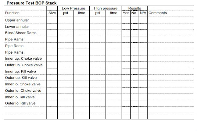
- You can use the below table to help you in your report.
General Testing Procedure For BOP With Cup Tester:
- Rig crews must be alerted when pressure test operations are underway. Only necessary personnel shall remain in the test area.
- All tests shall be performed using clear water.
- BOP equipment (including blind rams and shear blind rams) shall be pressure tested as follows
- When installed
- Before drilling out each string type of casing or casing liner
- Following the disconnection or repair of any wellbore pressure seal in the wellhead/BOP stack (limited to the affected components only)
- Not to exceed 14 days (± 2 days)
- The high-pressure test is specified in the following sections by the BOP class.
- The low-pressure test of each piece of BOP equipment shall be conducted at a pressure of 300 psi.
- The low-pressure test shall be performed first. DO NOT test to the high pressure and then bleed down to the low pressure. The higher pressure could initiate a seal after the pressure is lowered, thereby misrepresenting the low-pressure test.
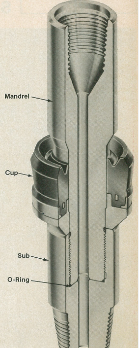
- Vent the cup tester through the drill pipe when testing procedure the upper 60 feet of the casing to prevent possible leaks from rupturing the casing or applying pressure to the open hole.
- All valves downstream of the tested valve shall be placed in the OPEN position.
- OPEN casing valves to the atmosphere when using a test plug to test the BOP stack to prevent possible leaks from rupturing the casing.
- Casing rams shall be tested to the maximum anticipated surface pressure, with a casing joint connected to a test plug with appropriate cross-over.
- OPEN annular valves when testing to prevent pack-off leaks from pressuring up outer casing strings.
- Continue the procedure by testing all valves on the wellhead individually to their rated working pressure on installation (using a VR plug) and to 80% casing burst on subsequent pressure tests, with a cup tester located + 90’.
- Variable Bore Rams (VBR) shall be tested with all pipe sizes, excluding drill collars and bottom hole assembly components.
- DO NOT close annular preventers on open hole or pipes with ESP cable (or wireline) for pressure tests. Annulars shall only be closed in these situations in an emergency. Annulars shall be tested with the smallest OD pipe to be used.
- The initial pressure test performed on hydraulic chambers of annular preventers should be at least 1500 psi. Initial pressure tests on hydraulic chambers of rams and hydraulically operated valves should be to the maximum operating pressure recommended by the manufacturer. The test should be run on both the opening and closing chambers. Subsequent pressure tests on hydraulic chambers should be upon re-installation.
- Only authorized personnel shall go into the test area to inspect for leaks when the equipment is under pressure.
- Tightening or repair work shall be done only after pressure has been released and all parties have agreed that there is no possibility of trapped pressure.
- A pressure test is required after the installation of casing rams or tubing rams.
- This test is limited to the components affected by the disconnection of the pressure containment seal. In the procedure, you should test the bonnet seals and rams using a test joint connected to a test plug or cup tester with appropriate crossover.
- Test stumps are an acceptable method for pressure testing the BOP stack at the rig site. The bottom connection (and any other connection not tested) must be tested with a test plug upon installation of the BOP stack.
- All pressure tests must be held for a minimum duration of ten (10) minutes with no observable pressure decline.
- All pressure tests shall be conducted with a test pump. Avoid the use of rig pumps for pressure testing. Cement units (cementing tools) are acceptable.
- All test results must be documented on a pressure chart, with the following information,
- Date of Test
- Driller
- Toolpusher
- Well Name
- Rig Drilling Supervisor
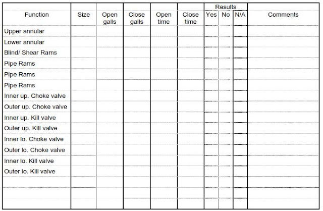
BOP Function Test
Function test all the BOP stack functions as per the below table
Checklist To Be Used While Rig Accepting BOP Stack
- Annular Preventer: Serial number – Size, make, and type as per the contract- Date of last annular packer installation
- Single RAM Preventer: Serial number – Type and equipment as per contract – Date of last general overhaul Rams size installed
- Double RAM Preventer: Serial number – Type and equipment as per contract – Date of last general overhaul Rams size installed
- BOP Drilling Spool: Number and size as per contract
- Adapter Spools to connect BOP with W.H: Number and size as per contract
- KILL & CHOKE Valves On BOP stack: Kill valves as per contract – Choke valves as per contract:
- KILL & CHOKE Lines (Also check: Choke Manifold): Kill lines dimension as per contract – Connected as per the contractual drawing – Dimension as per contract – Choke lines dimension as per contract
Other Items For BOP Acceptance Testing
- H2S monitor sensor heads at the top of the bell nipple, in the flow line
- One combustible gas detector installed, with the sensor at either the top of the bell nipple (or the flow line opening to the shale shaker if a rotating head in drilling is in use)
- BOP scaffolding or working platforms in good condition
- BOP ram locks are in working condition, and the operating handles are in place (API RP 53)
- The safe working load is marked on the trolley beams of BOP handling equipment.
- HCR remote valves are provided with a hand wheel as mechanical over-ride enabling the crew to close the valve manually.
- BOP (Coflexip) hoses are fire resistant
- Fall arrestor devices are available, inspected, and properly stored.
- Kill and choke lines of proper size and pressure rating per specs and fire resistance.
- All electrical junction boxes and conduits are sealed.
- Electrical equipment and cables are in good condition and explosion-proof.
- Lights with protective covers and explosion proof
- All pins and safety pins are in place.