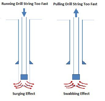
Surging or swabbing pressures in drilling describe pressure changes in the annulus resulting from pipe movement. The swabbing occurs when the drill pipe is pulled from the well, forcing mud to flow down the annulus to fill the void left by the pipe. However, the surging occurs when the drill pipe is lowered into the well. Then, the mud is forced out of the flow line. Pressure changes caused by lowering the pipe into the well are called surge pressures and are generally considered to be added to the hydrostatic pressure. This article will handle the swab and surge in drilling risks and calculations.
What Are The Risks Of Increasing Surging or Swabbing Pressures While Drilling?
Removing the drill pipe from the well creates swab pressures, which are harmful, resulting in a net lowering of pressure in the well. Many problems are caused by the swab and surge pressures. Removing the drill pipe at rates that create considerable swab pressures can induce well kicks by lowering the wellbore pressure below formation pressure, leading to a well control issue. Surge pressures increase the total wellbore pressure and can cause formation fracturing and lost circulation.
Swab And Surge Calculations
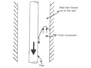
Computing the swab and surge pressures in drilling is difficult because the fluid flows as the pipe moves in the well. As shown in Fig. 1, the drill pipe moving down the annulus causes the mud adjacent to the pipe to be dragged downward. However, since the annulus is a fixed volume and the mud is considered incompressible, some drilling fluids must flow out of the annulus. The mechanics are different from pumping since the fluid flow is considered only one direction.
Burkhardt model For Surging And Swabbing Calculations In Drilling
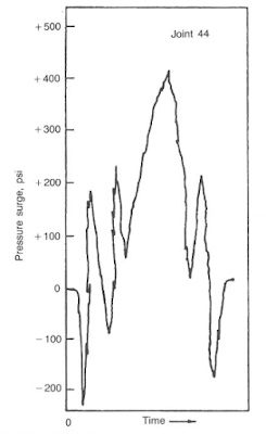
Burkhardt conducted drilling field studies to evaluate surge and swab pressures. His work involved running casing into a drilled well equipped with pressure sensors. A typical pressure response to the pipe movement is shown in Fig. 2. Positive and negative pressures are shown for the cases of the pipe being lifted off the drilling slips and later decelerated.
The complex fluid flow model shown in Fig.3 was evaluated by Burkhardt. Using involved mathematics, Burkhardt developed a relationship between pipe and hole geometries and the effect of the dragging mud adjacent to the pipe. The term clinging constant represents this relationship (Fig.4)
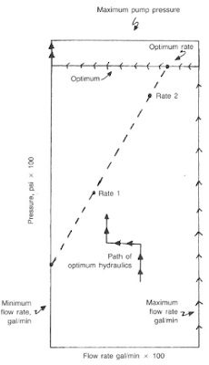
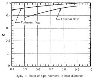
The mud velocity in the annulus must be computed before the clinging constant can be applied.
The flow rate of steel for a closed drill string into the well is given by Eq.1
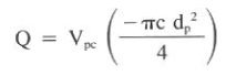
Where:
- Q = flow rate, gal/min
- Vp = pipe velocity, ft/sec
In swab and surge, the velocity in the annulus is the quotient of flow rate and area:
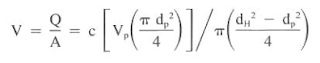
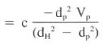
If the pipe is open-ended, the flow velocity is solved in a similar manner:
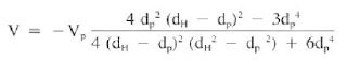
Applying the clinging constant, k, the effective annular velocity (Vc) is as follows:
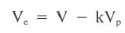
Burkhardt noted that clinging constant (k) = 0.45 was a good assumption for most typical geometries. In operation, a pipe velocity is used to compute the pipe flow into the well, which is assumed to be equal to the flow out of the well. The clinging constant is applied to yield an effective velocity based on the complex flow patterns in the annulus. The surging or swabbing pressures in drilling are computed by substituting the effective velocity into any of the previously defined friction pressure equations. It is reasonable to use laminar flow equations since normal pipe velocities seldom cause greater than critical velocities.
Example
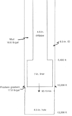
A well is experiencing lost circulation problems at the bottom of the casing string. A casing liner (One of the Types Of Casing) will be run into the well. If the liner is lowered at a maximum rate of 93 ft/min, will the surge (not swab) pressures exceed the fracture gradient? Use the Bingham model and assume laminar annular flow. In addition, assume the peak pipe velocity is the same as the average value. (Assume the liner has a closed end from a float shoe).
- casing depth = 10,000 ft, casing ID = 8.5 in.
- open hole depth = 13,000 ft, open hole OD = 8.5 in.
- liner size = 7 in. (flush joint), liner length = 3,600 ft, drillpipe = 4.5 in.
- mud = 16.6 Ib/gal, 38 cp (PV), 15 Ib/l00fe (YP)
- fracture gradient = 17.0 Ib/gal
- pipe velocity = 93 ft/min = 1.55 ft/sec
Solution:
1. The maximum surge pressures in drilling occur when the bottom of the liner reaches the casing seat (see Fig. 5).
2. The mud flow rate leaving the well when the liner shoe reaches the casing seat is:
V = Q / 2.448 (d^2)
Q = 2.448 V (d^2) = 2.448 (1.55 ft/sec) (4.5 in.)^2
Q = 76.8 gal/min
3. Compute the annular velocities around the drill pipe (Vap) and the liner (Val)
Vap = Q / 2.448 (dH^2- dP^2) = 76.8/ 2.448 (8.5^2- 4.5^2) = 0.603 ft/sec = 36 ft/min
Val= Q / 2.448 (dH^2- dP^2) = 76.8/ 2.448 (8.5^2- 7^2)= 1.349 ft/sec = 80.9 ft/min
4. To calculate surge and swab in drilling: Refer to Fig. 6 and determine the clinging constant, k, for the pipe and liner:
pipe – ratio = 4.5/8.5 = 0.529
k ≃0.38
liner – ratio = 7/8.5 = 0.823
k ≃0.45

5. The effective annular velocities around the pipe (Vpe)and the liner (Vle) are:
Vpe = V – 0.38 Vp = (0.603) – (0.38) x ( – 1.55) = 1.192 ft/sec
Vle = V – 0.45 Vp = (1.349 ft/sec) – (0.45) x( – 1.55) = 2.046 ft/sec
6. The pressure surge caused by the drill pipe using Bingham model for Laminar flow is as follows (use Eq.6):
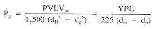
Pp = {(38)(6,400)(1.192) / 1,500 (8.5^2 – 4.5^2 )} + {(15)(6,400) / 225 (8.5-4.5)}
Pp = 3.716 psi + 106 psi = 110 psi
7. The pressure surge caused by the liner is:
Pl = {(38)(3,600)(2.046) / 1,500 (8.5^2 – 7^2 )} + {(15)(3,600) / 225 (8.5-7)}
Pl =8.0 psi + 160 psi = 168 psi
8. The total pressure surge and equivalent mud weight is:
110 psi + 168 psi = 278 psi
EMW = pressure x 19.323 / depth + mud weight
EMW = 278 psi x 19.23 / 10000 ft + 16.6 lb/gal = 17.13 lb/gal
9. Therefore, the fracture gradient of 17.0 Ib/gal would be exceeded (17.1 Ib/gal) at a pipe velocity of 93 ft/min.
10. In reality, the flow regime in the annulus was turbulent opposite the liner. The assumption of laminar flow in this example was done for the swab and surge drilling calculations simplicity and illustration
Notes About Surg & Swab Pressures Calculations In Drilling
An open-ended pipe increases the complexity of the calculations considerably. Pressure drops in the annulus and drill string must be equal. Since different geometries exist, flow rates in the annulus and pipe will not be the same. In addition, it is possible that the annulus will be laminar while fluid flow in the pipe will be turbulent.
A trial-and-error solution assumes a significant percentage of the flow will be up the annulus, with the remainder in the pipe. Pressure losses are computed and compared from these assumed volumes, and the volumes are adjusted depending on the computed pressure relationships. If the first trial was a 75:25 annulus-to-pipe ratio and a pressure distribution of 200:300 psi was observed, a second trial might be at 80:20. The procedure is iterated until a ratio is obtained that yields equal pressure drops in both the pipe and annulus.
In a practical sense, surge and swab pressures in drilling are composed of the pressures required to break the gel strength in the mud and the pressures caused by actual fluid movement. Thick muds often produce such high gels that surge pressure from this component is significant. The yield point (check also Yield Point In Drilling Mud) and gel strength of the mud affect this type of pressure.
What Is The Maximum Allowable surge & swab Pressure?
If a maximum allowable swab or surge pressure is known, it is possible to determine a maximum pulling or running speed for the pipe.
- The maximum surge pressure usually differs between the lowest exposed fracture gradient and the mud weight.
- The maximum swab pressure differs between the most significant formation pressure from an exposed permeable zone and the mud weight.
Accordingly, the swab pressure equations are solved in reverse order to arrive at a pipe velocity.
Example:
Refer to the data in the above Example. If the drilling engineer at the well site does not wish to exceed a 16.9-1b/gal equivalent surge pressure, what is the maximum velocity at the pipe can be run into the well?
Solution Of swab ad surge calculations:
1. Determine the maximum allowable surge pressure so the 16.6-1b/gal mud does not exceed the 16.9-1b/gal equivalent value:
maximum allowable surge pressure = 0.052 x (16.9 – 16.6) x(10,000ft) = 156 psi
2. The 156-psi surge pressure is the maximum amount that can be generated by the friction pressure opposite the pipe and liner, or: 156 shall be lower than or equal to Pp+ Pl
3. Substituting the pressure equations for Pp & Pl:
= { (38) (6,400) (Vpe) / 1.500 (8.5^2 – 4.5^2 ) + (15) (6,400) / 225 (8.5^2- 4.5^2) } + { (38) (3,600) (Vle) / 1.500(8.5^2 – 7^2 ) + (15)(3,600) / 225 (8.5- 7) }
= 3.118 Vpe + 3.922 Vle+ 266 psi
156 psi shall be lower than or equal { 3.118 Vpe + 3.922 Vle+ 266 psi }, which can be rewritten as follows to avoid surge and swap
110 psi shall be lower than or equal { 3.118 Vpe + 3.922 Vle }
Since the sum of the velocity components is negative, the pipe cannot run into the well at any velocity without exceeding the 16.9 Ib/gal limitation. The yield point component of the pressure surge, not the swab, will cause the pressures to exceed the 156 psi value.