The liner hanger system is installed at the top of the casing liner (One of Types Of Casing). The function of the liner hanger is to hang and suspend the liner. There are mechanical liner hanger and hydraulic set hangers. In this article, we will provide detailed steps for Liner Hanger Setting & Cementing Procedures.
The main two types of Liner Hanger are:
- Mechanical liner hangers require manipulation of the Drill Pipe (Check also: Drill Pipe Specifications) to engage the hanger slips with the casing.
- Slips of the hydraulic hanger engage the Casing (Check also: Our guide to casing design calculations manual) by applying pressure. Hydraulic hangers are used in deep or highly deviated wells where it is difficult to transmit pipe manipulation to the hanger because of excessive friction between drill pipe and casing ( Check also Drilling Torque & Drag Calculation & Spreadsheets ).
Float Equipment & Liner Accessories Required For Liner Setting & Cementing Procedures
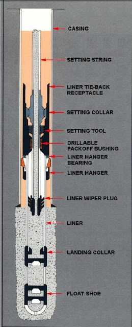
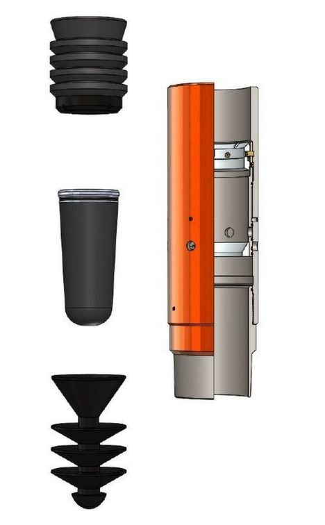
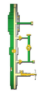
A liner is normally run on Drill Pipe that extends from the liner setting tool to the surface. Special tools are available to perform various liner running, setting, and cementing procedures. The following equipment is discussed from the float shoe to the cementing manifold. Equipment locations are shown above.
Float Shoe
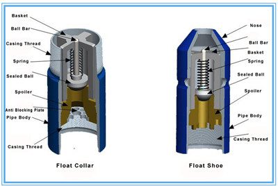
A float shoe is placed at the bottom of the liner. It contains a check valve to prevent back flow of the cement while liner cementing procedures.
Float Collar
A float collar can be installed 2 joints above the shoe to provide a backup check valve to assure that cement cannot re-enter the liner after displacement.
Latch Collar
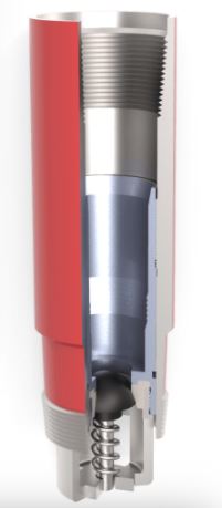
A latch collar is run one joint above the float collar or two joints above the float shoe to provide space for mud contaminated cement inside the liner. The latch collar’s function is to latch and seal the liner wiper plug. It prevents the wiper plug from moving up the hole if a check valve fails and also it prevents it from rotating, which aids in the drilling out operation.
The liner length is selected to extend across the open hole to overlap the existing Casing or stage tool. The length of the overlap should provide a good cement seal in the liner-casing annulus. A 300 ft overlap is normally used and a 400-500 ft overlap is used in deep high pressured wells.
External Casing Inflatable Packer
If required, an external casing inflatable packer is run to cement the liner in two stages. The packer is run with a DV tool port collar set above super permeability or loss circulation stringer to allow placement of cement above the mud loss / Lost circulation zone.
The liner cementing job procedures are performed by pumping the first stage cement first and dropping the Drill Pipe plug. The cement and plug are displaced with drilling fluid until the DP plug latches in the liner wiper plug which is attached at the bottom of the liner setting tool. Pressure is applied to break the shear pins and release the wiper plug. Displacement is continued until the wiper plug and DP plug latch and seal in the latch collar. Pressure is applied to open the packer inflation ports. The packer is then inflated with mud or cement to provide a seal with the open hole above the lost circulation zone.
Higher pressure is applied to open the DV ports and cement is pumped above the packer to the top of the liner. The DV ports are closed by the DV shut-off plug.
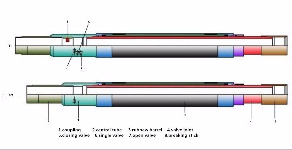
Liner Packer
Liner hangers may be equipped with a liner packer installed at top of the hanger to seal between liner and casing after cement placement procedures. Seal elements may be rubber, lead or both and are set by applying weight on the hanger. After the packer is set excess cement above the hanger can be circulated out without imposing high pressure on the formation below.
Liner Setting Tool
The liner setting tool, which is a rental item furnished by liner hanger service company, provides the connection between the Drill Pipe and the liner hanger.
Packoff Bushing and Slick joint
A packoff bushing and slick joint are inserted into the liner to provide a seal between the setting tool and the liner. Once the hanger is set and the liner is cemented, the setting tool is released from the hanger and pulled out to the surface.
The Liner Wiper Plug
The liner wiper plug is attached at the bottom of the setting tool with shear pin arrangement. The function of the plug is to separate the cement from the displacing fluid. Once the plug latches in the latch collar it provides a pressure seal and allows pressure testing the liner above the latch collar or inflating the external casing packer.
The Drill Pipe Plug
The drill pipe plug is dropped in the Drill Pipe after all the cement has been pumped. The plug is displaced by the drilling fluid until it latches with the liner wiper plug at the bottom of the setting tool. Higher pressure is applied to shear the wiper plug from the setting tool and both plugs are displaced with drilling fluid until they latch in the latch collar.
Preliminary Preparations For Liner Running, Setting & Cementing Job
- A meeting shall be held with key personnel to discuss the detailed program and operational liner setting and cementing procedure.
- It is recommended to make up the liner hanger system already as an assembly and test at the Contractor’s workshop including running tool, pup joints, plug holder bushing, packer extension, etc., checked, drifted, and measured.
- Under normal conditions, the liner will be hung with a 100 to 150 m overlap into the previous Casing. If a smaller overlap is necessary due to a particular situation, it shall never be less than 50 m.
- If the rat hole exceeds the overlap length, set a cement plug at a distance from the liner shoe setting depth (read more about casing setting depth) shorter than the overlap itself.
- Strap the Drill Pipe as it is pulled out of the hole on the last trip (check also tripping pipe procedures) before running the liner. Separate the Drill Collar, Bottom Hole Assembly BHA, and extra DP stands in the drilling rig derrick or rig mast according to the calculated running string for easy checking and operation.
- Drift the drill pipe and check the ID of all tools, subs, crossovers, and pup joints of the running string to ensure passage of the drill pipe pump down the plug and for dropping the ball for the hydraulic liner hanger.
- Visually inspect all tools and equipment for damaged components, dents, etc. Record the shear pressure of all shear pins.
- The liner hanger OD and packer extension sleeve shall be checked and the length measured.
- The liner cementing plug system (single or dual plugs) should have 1,500-2,000 psi shearing pressure to check the latch-in and verify the exact displacement volume (pump volumetric efficiency knowledge, which is important to have a correct final bump plug).
- A liner hanger assembly with a double plug cementing system ensures the appropriate cementing head with dual drill pipe darts is used.
Liner Running And Setting Procedures
1) Run & set the liner hanger with the following operational procedure
2) Check that the liner hanger slips operate properly and are undamaged before running & setting procedures (mechanical type).

3) According to the liner hanger design being used, check the proper distance between liner hanger setting tool stinger and casing plug receptacle for the correct latch-in plugs procedures.
4) Perform a circulating test at the liner hanger top to assure sealing of the packing elements (‘O’ ring or ‘V’ chevron).
5) Under no circumstance shall rotation be allowed to the running string; use a backup tong for connection make-up, and lock the rotary table (mechanical type).
6) At every circulation point before the hanger setting (previous casing shoe, open hole or bottom), keep circulating pressure at a maximum of 80% of the hanger slip setting value (hydraulic type).
7) Record the exact liner and DP string weights including drag (hook load down and up) to calculate the exact neutral point for the setting tool release (10-15 T bearing).
8) When the liner setting depth is reached, start reciprocating slowly. Break circulation pumping very slowly (100-300 lpm), then increase the flow rate to the desired value (observe for pressure surges to avoid formation fracture) and condition the mud as per the program.
9) Remove the kelly, drop the setting ball, install the cementing head with the swivel (drill pipe dart plug inserted) and indicate flag. Prepare the rig floor by-pass manifold with double lines and valves for direct and reverse circulations.
10) After mud and hole conditioning, set the hanger following the procedures provided by the manufacturer. If circulation time is greater than 60 min, set the hydraulic hanger before completing the circulation and with the bottoms up above the liner head (minimum circulating volume before dropping the setting ball is the DP plus Casing capacity).
11) Release the setting tool and pick up circa 3ft (1m) to ensure that it has been released (never pull the stinger out of the packing or dogs above the packer’s extension sleeve).
12) For heavy liner or high-angle wells, use a long stinger and packing (>3m) and packer extension sleeve.
Liner Cementing Procedures
1) Cement the liner as per the Cementing Program procedures. Excess cement slurry will be as programmed (preferred 20 % of the caliper data volume), based on slurry return at the top of the liner. The slurry must be batch-mixed.
2) Design a proper and compatible spacer to separate the drilling mud from the cement slurry (for 150m of the annulus with a balanced weight spacer, possibly with 8-10 minutes of contact time).
3) Displace the cement with the cementing unit on shallow liners. Use the rig pumps for deep liners.
4) If no shear of the wiper plug is observed, do not bump the plug. Use the theoretical displacement volume only.
5) Reduce the pump rate to 300-400l/min, 1-2m3 before the expected bump plug. Once the theoretical volume has been displaced, if the plug does not bump, over displace a maximum of 2/3 of the shoe track volume (between the landing collar and the float shoe).
6) Bump the plug with 500-1000 psi above the final displacement pressure. However, the bumping plug value will be stated in the drilling program.
7) Bleed off the pressure very slowly and check for backflow.
8) Pressurize approx. 300 psi to check the correct sting out. Pick up the setting tool and circulate at least twice the annulus capacity while moving the string.
9) Pull the setting tool. In the case of a liner hanger equipped with a CPH packer, the following un-setting liner hanger procedure has to be followed:
- Pressurise to approx. 300 psi to check the correct sting out.
- Pick up the setting tool, with activating dogs above the extension sleeve head, and apply the appropriate weight to energize the CPH packer.
- Pick up the setting tool above the extension sleeve and circulate at least twice the annulus capacity.
Liner Running, Setting & Cementing Animation
This is a good video explains the procedures to RIH and performing cement job for liner Casing string.