Objective:
- Airated and Foam Drilling Mud Application.
- What is Aerated Drilling Mud
- What is Foam Drilling Mud
- What is The Required Equipment for Aerated & Foam Drilling Muds
- Recommended operating procedures for Aerated & Foam Drilling Mud
- Determining hydrostatic loss caused by gas-cut mud
- Corrosion Caused By Foam & Aerated Drilling Fluids
- Conclusion
- Learning Videos For Aerated & Foam Drilling Mud Fluids
- Useful Papers Related To Aerated & Foam Drilling Mud Fluids
Air, Aerated, and Foam Drilling Mud Applications
Aerated fluids used in drilling operations include air, natural gas, mist, foam, or aerated muds. These fluids allow high penetration rates because of the reduced hydrostatic pressure, thus allowing the drilled rock fragment to explode into the wellbore. Lost circulation problems are minimized when using aerated fluids.
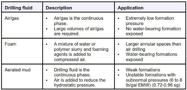
Air drilling uses air volume to drill formations that present major problems for drilling fluids. Foam is a combination of water or polymers/bentonite slurry mixed with a foaming agent; air from a compressor combines with the foaming agent to form the bubbles that act as carrying agents for cuttings removal. Aerated mud can be virtually any Water Based Mud to which air is added. This type of mud has less hydrostatic pressure and less tendency to fracture weak formations. Foam and aerated muds are useful when air drilling is impossible and drilling fluids are inefficient.
When normal drilling fluids are inappropriate, air, foam, and aerated mud are effective alternatives. These fluids can be used when drilling the following formations:
- Extremely porous formations
- Subnormally pressured formations
- Cavernous formations
Table 1 explains how each fluid is used.
Air drilling
Air drilling uses compressed gas for hole cleaning. Air is the most commonly used gas, but natural gas and other gases can also be used.
Problems that can be encountered with gas drilling include:
- Regulation of gas pressure.
- Influxes of formation fluids.
- Erosion of the wellbore.
As the stream of gas and cuttings erodes the wall and widens the annulus, a greater increase in gas volume is required to maintain gas velocity. Sometimes water or mud is misted into the well to inhibit shales and reduce Torque And Drag.
The most important aspect of gas drilling is Mud Hydraulics, in other words, maintaining an adequate annular velocity. If the annular velocity falls below the point where it can clean the hole, the cuttings will accumulate and cause a Stuck Pipe. An annular velocity of 3,000 ft/min is normally required for air drilling.
Foam Drilling Mud
Foam drilling Mud uses foam as the carrying agent for cuttings removal instead of air velocity. Foam drilling requires less volume than air drilling and relies on bubble strength to remove cuttings, while air and mist drilling depends on extremely high flow rates. An indication of effective foam drilling is a continued and regular foam flow at the blooey line.
A pulsating, irregular flow (heading) can indicate problems with the flow columns. In addition to hole cleaning, the foam deposits a thin filter cake on the hole’s walls to improve borehole stability. To thicken foam and improve hole cleaning and water tolerance, polymers and/or bentonite are used to mix a slurry for injection.
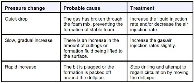
Surface injection pressure
Foam drilling Mud is most effective when the lowest possible StandPipe Pressure is maintained. Pressure on the standpipe can range from 80 to 350 psi. Changes in the standpipe pressure are the best way to detect drilling problems. As pressure changes are identified, adjust the foam injection rate and the gas volume percentage to deal with the change. Table 2 provides corrective adjustments for different types of pressure changes.
Use these guidelines to manage the foam-drilling Mud system.
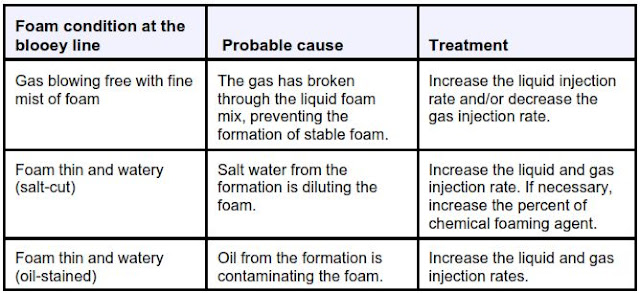
Condition of foam at the blooey line
Under normal drilling conditions, foam at the blooey line should be similar in appearance and texture to shaving cream foam. If the foam is not thick or does not hold its shape, adjust the rates of gas and foam-solution injection. Consult Table 3 for appropriate steps.
Use these adjustments to correct foam-based drilling mud on observation at the blooey line.
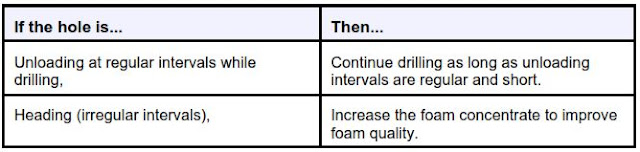
Heading or regularity of foam return at the blooey line
For optimal removal of cuttings, foam returns at the blooey line should be continuous. Heading and unloading can indicate problems with the foam column.
Aerated mud
Aerated mud systems reduce lost circulation in areas with very low fracture gradients. At the same time, shale hydration and corrosion are minimized. Effective mud weights of 4 to 6 pounds per gallon (0.48-0.72 sg) are possible with an aerated system. These weights substantially reduce differential pressure in the wellbore. Because of the lower pressure, the driller (Check also Driller Job Descriptions) can reach a higher penetration rate than is possible with normal drilling fluids.
The following equipment is needed for an aerated drilling mud system:
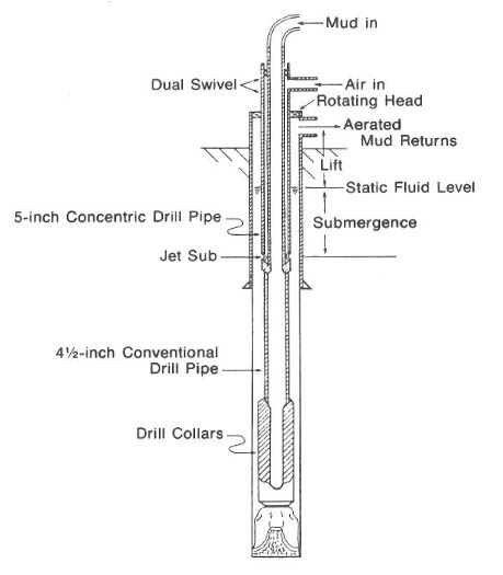
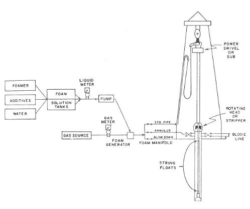
Drilling equipment for aerated mud is basically the same as OBM and water-based mud, except compressors and rotating heads. The compressors are analogous to mud pumps. The rotating head diverts the high-velocity air in the annulus through the blow-down line Fig.1 & Fig.2
- An air compressor capable of 850 SCFM
- A backup compressor capable of 850 SCFM
Note: When comparing compressor ratings, remember that ratings are made at sea level. Adjust the ratings as necessary to allow for the altitude at the drilling site.
- An air bypass (or other means of limiting the air volume) when the total compressor capacity is not required, as with a surface hole
- A Barton recorder for gauging the actual CFM of air injected
- A rotating head to direct the air and mud flow out of the flow line instead of up through the rotary table or over the drilling nipple into the cellar
Note: The rotating head should be maintained to prevent mud loss at the head, which may cause the-end well control problems. If the drilling crew is not paying close attention, an undetected loss at the head can be mistaken for lost circulation in the hole.
- An air-mud separator (gas buster) at the flowline
Note: The separator is typically a cylindrical tank 3 to 6 feet in diameter and 8 to 10 feet high with baffles to help break the air out of the mud.
- An air vent on the top of the tank aimed toward the reserve pit
Note: This vent also accommodates overflow when the return is hard
- A mud flow discharge on the bottom of the tank for discharge into the possum belly
Recommended operating procedures for Aerated & Foam Drilling Mud
When using Aerated Drilling Mud systems:
- Inject air into the standpipe and arrange the piping so air can be bypassed at the floor for making connections, etc.
- Plumb the piping so the mud can be pumped downhole while air is bypassed.
- Run the Oilfield Drilling Bit with open water courses (no jets) to prevent excessive air pressure requirements. With the reduced bottom hole pressure, jet impact is not as critical for cleaning the bottom of the hole.
- Larger drill pipe sizes (API Drill Pipe Specs) of 4 1/2 or 5 inches are recommended to reduce compressor volume requirements.
- Filling the hole between trips (check also tripping pipe procedures) is not necessary with aerated mud.
- Circulate the mud system at a constant rate of 6 to 8 bbl per minute and treat it as normal. Do not vary pump output to maintain constant bottom hole pressure or to control gains and losses; instead, regulate the airflow to correct these problems.
- Use the aerated mud chart to determine the amount of air to inject to achieve a specific reduction in bottom hole pressure.
- Install float valves in the drill string approximately every 200 feet (61 meters) to prevent back flow on connections.
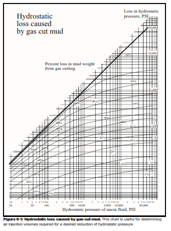
Determining hydrostatic loss caused by gas-cut mud
To find Bottom Hole Pressure (BHP) loss due to gas-cut mud:
- Find the hydrostatic pressure of uncut mud.
- Start with hydrostatic pressure at the bottom of the chart. (See Figure 6-1.)
- Proceed up to intersect percent gas in mud.
- Read on right to the BHP loss due to gas content.
- Subtract loss from original BHP to find a new effective head of gas-cut mud.
Moderate gas cutting reduces measured mud weights on the surface but produces little effect on the effective hydrostatic head at depth due to gas behavior under pressure.
When minimum overbalances are being used or gas cutting becomes severe, an accurate method of determining the BHP reduction is needed. (See note below.) This graphical solution disregards the effect of gas density and thus provides a tool useful for either gas or air. As such, it becomes useful for determining air injection volumes required for a desired reduction of hydrostatic pressure.
Note: White, R. J. “Bottom-Hole Pressure Reduction Due to Gas Cut Mud,” Journal of Petroleum Technology, July 1957.
Corrosion Caused By Foam & Aerated Drilling Fluids
Aerated and Foam Drilling Mud fluids can be corrosive. The injected air contains carbon dioxide and oxygen that promote corrosion. Inhibitors are needed to counter the effect of these gases. The products in the following table are recommended for corrosion problems.
Conclusion
Problems associated with air or natural gas drilling are often due to insufficient air volumes for removal of the cuttings. Annular velocity below 2,500 ft/min may not remove the chips. In addition, these high velocities commonly erode and enlarge the wellbore such that a volume previously satisfactory before the erosion will not lift cuttings after the erosion. Surface flow restrictions should be minimized because of the ease at which air or natural gas can be compressed, thereby reducing its flow rate. The approximate required circulation rate for air drilling can be calculated with Eq.1. The equation is based on a minimum annular velocity of 3,000 ft/min to lift the water with air.
Mist or foam drilling mud is an alternate procedure for lifting cuttings from the hole while reducing the annulus hydrostatic pressures. These fluids with higher viscosities than air or gas do not require high flow rates. For example, a stable foam may require only 200-300 ft/min to clean the annulus. Common mud additives for air systems are detergents for foaming, corrosion inhibitors, lubricants for friction reduction, and viscosifiers such as CMC.
Aerated muds are used when greater lifting capacity is required and reduced hydrostatic pressure is desired. Air is injected into the mud at the standpipe, circulated down the drill string, and channeled up the annulus, where it expands and reduces the hydrostatic pressure. The required air volume can be computed with Eq.1 & 2:
Where:
- n = volume percent of the air in the air-mud mixture at wellhead discharge pressure
- D = depth, ft
- Wi = initial mud weight, lb/gal
- Wf = desired final average mud weight, lb/gal
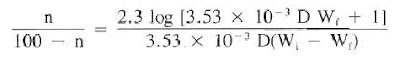
The ratio n/(100 – n) is the value of cubic feet of air per cubic foot of mud at surface flowline pressure:
Where:
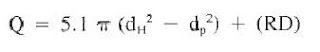
- Q = required flow rate, cu ft/min
- dH = hole diameter, in.
- Dp = pipe diameter, in.
- R = expected drill rate, ft/hr
- D = well depth, 1,000 ft
Field experience has shown that the results from Eq.2 may be 15-20% above the required volumes for dry drilling and possibly 15-20% below the necessary amount for most drilling.
Helpful Videos For Aerated & Foam Drilling Mud Fluids
Aerated Drilling Fluid Process Video
The drilling fluid processes for standard, aerated, and 3M Glass Bubble additive drilling fluids are demonstrated within these three animations, illustrating the equipment required.
Aerated drilling on SJ 04 Video
Drilling with air (connection)
Typical connection while drilling with air (mist) in the Barnett Shale on H&P rig 263. The operator liked breaking out with a little air still in the string so that it didn’t take so long building air after the connection. You can get stuck pretty quick when drilling with air.
Useful Papers Related To Aerated & Foam Drilling Mud Fluids
The Use Of Aerated Drilling Fluid Technique Through Top Fractured Formations In A Deep Gas Field – A Case History

The aerated drilling fluid technique was introduced to a deep gas well drilling project as a solution to overcome the challenges posed by top fractured formations and highly water-sensitive shales. The top holes were originally drilled with a diesel oil-emulsion drilling fluid, which was later changed to a high-bentonite content drilling fluid system. The aerated drilling fluid aims to improve the overall drilling performance and address top-hole geological complications.
This paper will describe in length the performance of the trial jobs, present the lessons learned from implementing this innovative drilling fluid technique, and highlight the best practices utilized to make it a cost-effective solution.
Volume Requirements for Aerated Mud Drilling
Aerated mud is defined as a fluid consisting of liquid (usually water), air, and drill cuttings. It can be shown that the theories on gas/solid two-phase flow developed for air and mist drilling and theories on liquid/gas two-phase flow developed for oil production through tubing are inaccurate when applied to aerated mudflow in an annular wellbore. Therefore, Guo et al. proposed a mathematical model for describing a wellbore’s three-phase (air, water, and cuttings) flow. The modeling was validated by a comparison with field data obtained from aerated mud drilling. This paper uses the developed model to determine the liquid and air volume requirements considering the cuttings-carrying capacity of the aerated mud, wellbore stability, pressure-differential pipe sticking, and formation damage.
How to download the notes
Great job..