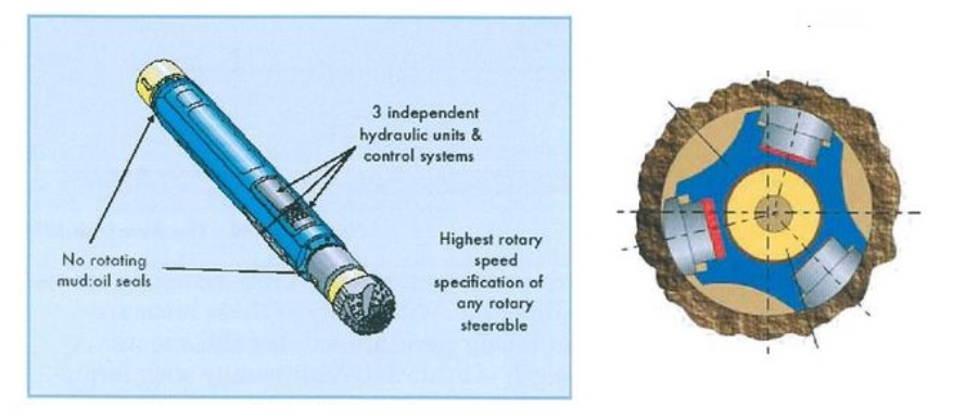
The Baker Hughes AutoTrak RSS (Rotary Steerable) uses a non-rotating sleeve close to the drilling bit. The sleeve utilizes three independent hydraulic and control systems. The hydraulic pistons can push the bit to one side of the hole. And therefore, changing the wellbore’s inclination and/or direction (Figure 1).
We can integrate the RSS AutoTrak with LWD systems such as Gamma Ray, Neutron Density, Calliper, etc. With many of these measurements being at the bit and without a long conventional downhole motor assembly, a much reduced BHA length is achieved. Additionally, with formation measurements much closer to the bit, we can achieve an improved geosteering capability.
In addition to the AutoTrak system, BHI markets a vertical drilling system called VertiTrak.
Baker Hughes RSS Principle Of Operations
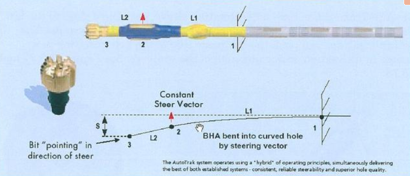
The AutoTrak system consists of a “Hybrid” operating system that can push or point the bit in a certain direction. The AutoTrak Rotary Closed Loop System (RCLS, Figure 2) determines the operating mode for the wellbore’s immediate requirement. It will push the bit immediately to the side when initiating a change to a wellbore trajectory (e.g., ending a tangent, starting a 3-D turn, etc.). Once drilling a few feet of the new curvature, the steering mechanism will bend the bottom hole assembly into the new curvature. Then, It will effectively point the bit in the required direction.
The Rotary Closed Loop System (RCLS) incorporates an automatic drilling mode in which a near-bit sensor measures the inclination continuously. The measurement will be at 5 seconds intervals. These measurements are fed into the tool’s downhole logic system, which compares the near-bit inclination trends to the Target Inclination programmed into the system’s downhole memory within a small fraction of a degree. If the inclination trends are of greater value than the Target Inclination, the tool automatically steers down to drop inclination and vice versa. When there is a requirement by the well plan, we can reset the target Inclination value by downlinking to the tool from the surface.
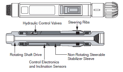
Figure 3 shows a BHA with the bit, the non-rotating sleeve (2), a rotating stabilizer (Ll), and the electronic control unit (1).
Baker Hughes RSS Rotary Steerable (Autotrak) Components
The main elements of the Baker Hughes Autotrak rotary steerable system are:
- Downhole System
- The Non-Rotating Steerable Stabilizer;
- The electronics probe and
- The Reservoir navigation or MWD drilling tools.
- The Surface System
- Surface Computer System
- By-Pass Actuator
Baker Hughes Autotrak Non-Rotating Steerable Stabilizer
The Steering Unit contained within a non-rotating sleeve controls the direction of the bit (Check Also: Types Of Drilling Bits). A drive shaft rotates the bit through the non-rotating sleeve. The sleeve is decoupled from the drive shaft. Therefore, drill string rotation will not affect the sleeve.
This sleeve contains three hydraulically operated ribs, the near-bit inclinometer, and control electronics. Pistons – operated by high-pressure hydraulic fluid – exert controlled forces separately to each of the three steering ribs. The system applies a different, controlled hydraulic force to each steering rib, and the resulting force vector directs the tool along the desired trajectory at a programmed dogleg severity.
A combination of downhole electronic control adjusts this force vector and commands pulsed hydraulically from the surface.
The micro-processing system inside the Baker Hughes Autotrak RCLS calculates how much pressure we can apply to each piston. Therefore, we can obtain the desired toolface orientation.
In determining the magnitude of the force applied to the steering ribs, the system also considers the dogleg limits for the current hole selection.
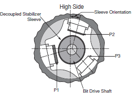
In field tests, the sleeve has been seen to rotate at approximately one revolution every W hour. This will depend on the formation type and ROP. To compensate, the system continuously monitors the relative position of the sleeve. Using these data, Baker Hughes Autotrak RCLS automatically adjusts the force on each steering rib. This will provide a steady side force at the bit in the desired direction.
Electronics Probe
The Electronics Probe controls the interface between all tool components and manages data exchange to and from the surface. This section also contains directional and tool vibration sensors. Azimuth measurements from the tri-axial magnetometer monitor and control the steering unit in conjunction with the near-bit inclinometer, providing early readings of tool inclination changes. The vibration sensor helps ensure Baker Hughes RSS RCLS is operated within specifications and at maximum efficiency.
Reservoir Navigation Tool / MWD
The Reservoir Navigation Tool (RNT) sub – (Drilling Subs) with Multiple Propagation Resistivity (MPR) and Dual Azimuthal Gamma Ray (GR) sensors – enables real-time geosteering within the reservoir. Using two frequencies and dual transmitters, the RNT provides four (4) compensated resistivity measurements for accurately determining Rt under various conditions. The system provides deep-reading 400 kHz measurements and high vertical resolution 2 MHz readings.
While drilling horizontally, the 400 kHz readings can detect contrasting bed boundaries and fluid contacts up to 18 feet (5.5 m) from the tool. A horizontal application enables drillers to anticipate boundaries more than 250 ft (75 m) ahead of the bit. These two frequency readings and Dual Azimuthal, Gamma Ray measurement, enable Baker Hughes Autotrak Directional Drillers to downlink course corrections to keep well in the zone of interest.
Surface Computer System For Baker Hughes RSS
The Surface Computer System encodes the downlink signals for transmission to the tool and decodes the Measurement While Drilling MWD signals received from the downhole. It also provides standard directional and LWD outputs. This system includes the central processor and an MWD decoding unit. We can control downlink communication with the Baker Hughes RSS RCLS tool by the computer or manually from the keypad. The downhole system is programmed using the negative pulse telemetry created in the surface By-Pass Actuator.
By-Pass Actuator
The By-Pass Actuator (BPA) valve unit transmits commands to the downhole tool through negative mud pulse telemetry. Each valve unit is fully certified by Det Norske Veritas. The by-pass actuator is connected to the standpipe and can divert some of the mud flow to create a series of negative pulses in the drill pipe. The tool senses and decodes these as downlink instructions.
A complete downlink command can take between 2 and 8.5 minutes, depending on the complexity of the downlink. After the Baker Hughes RSS RCLS downhole tool receives the downlink information, it returns a confirmation message to the surface, then reconfigures itself for the required task. We can perform automated downlink as drilling proceeds, allowing control of Baker Hughes Rotary Steerable RCLS without interrupting the progress of the well.