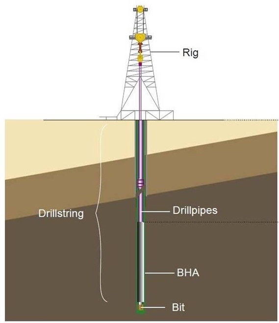
The first step in drill string design is designing a Bottom Hole Assembly (BHA). The BHA comprises various components that work together to enable drilling engineers to achieve their drilling targets. Designing a BHA involves several critical steps that drilling engineers must consider to ensure that the drilling operation is safe, efficient, and successful. In this article, we will examine the steps involved in designing a BHA and how drilling engineers carry out this process to achieve optimal results.
Drill Collar Size Selection
Unless mechanical hole sticking is a problem, the most oversized diameter drill collars & BHA consistent with other needs are generally best. Their increased stiffness means more directional and drill bit stability. Also, they will have fewer connections for a desired weight on bit and, therefore, a shorter BHA type, which can lessen the probability of differential sticking.
More oversized OD collars in a given hole also mean less lateral freedom of movement in the BHA. This decreases BHA buckling stress and the rate of connection fatigue. However, existing drilling rig inventory often determines drill collar size. Other factors which come into play are:
- Fishability considerations (Fishing Operations).
- Capabilities of the rig handling equipment.
- Directional drilling control requirements.
- Hydraulics
- Desired exterior features (spiral grooves, elevator grooves, or other features).
- Motor Power
Read More: Drill Collar Specifications
In conclusion, the largest BHA component diameter is generally best.
Length of Drill Collar Section In BHA Design
The Drill Collars are the first section of the Drill String to be designed, and their length and size affect the type of Drill Pipe that must be used. The length of the drill collar section is determined by the BHA type and, in part, whether or not HWDP is to be used for bit weight. The type of well being drilled determines the BHA configuration to use, i.e., whether the well is vertical, deviated, or horizontal.
One function of the drill string is to produce sufficient weight to drill the hole. So how many drill collars will you need to deliver the desired WOB? Two main methods are used in drill string design to calculate the drill collar weight.
Read more:
DCs Weight Calculations & Length Selection.
Selecting BHA Connections and Features
The following points apply to drill collars and Heavy Weight Drill Pipe from the rig inventory and to the many specialized tools that find their way into the hole. Stabilizers, Mud Motors, Measurement While Drilling and LWD tools, hole openers, under-reamers, Drilling jars, and many other tools are all subject to fatigue. When designing the BHA for the Drill String, the following should be considered when selecting BHA component connections:
- Bending Strength Ratio (BSR) or Stiffness Ratio (SR)
- Fatigue Resistance – Thread Type, Stress Relief Features, Cold Rolling, Material Properties (Charpy Value)
- Torsional Strength
Bending Strength Ratio
In the Bending Strength Ratio article, you will discover its definition ranges and can download its calculator.
BHA Connection Thread Form & Design
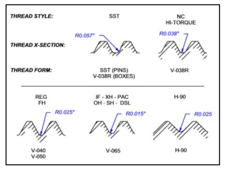
Thread forms with full root radii should maximize fatigue resistance in all BHA connections. API Regular, NC, and 5.1/2 Full Hole connections meet this requirement. However, the API NC thread form (V-038R) is superior to the others. The H90 thread form is also considered acceptable, even though it does not have a full root radius.
Stress Relief Features:
API rotary-shouldered pin and box connections on BHA equipment are prone to fatigue cracks initiating in the roots of the last engaged threads, as shown in the Figure below. These are the areas of highest stress concentration, and fatigue cracks developed here grow at an increasing rate until failure occurs.
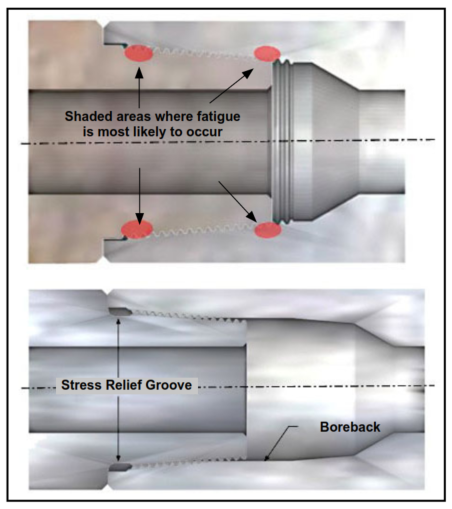
As described in API Spec 7, stress relief features should be specified on all BHA connections NC-38 and larger. These features include the “stress relief pin” and “boreback box”. They extend connection fatigue life by eliminating on-engaged thread roots, which act as stress concentrators.
Stress relief features are beneficial for HWDP connections. Pin stress relief grooves are not recommended for connections smaller than NC-38 because they may weaken the connection’s tensile and torsional strength. Fatigue is often less of a problem than static loads on small connections. Boreback boxes could be used on smaller connections without weakening them, and they should be considered if box fatigue occurs.
Cold Rolling:
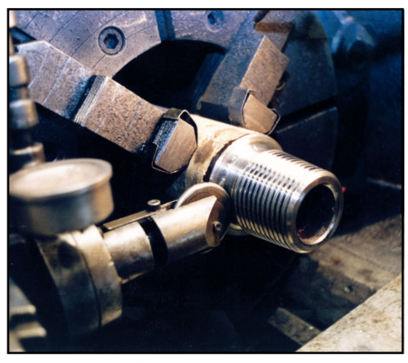
Cold rolling BHA thread roots and stress relief surfaces increase fatigue life by placing residual compressive stress in the thread roots. The figure below shows the cold rolling of an API Pin connection. This cold rolling also benefits HWDP threads, though not normal-weight drill pipe tool joints. Fatigue is rarely a problem on normal-weight drill pipe tool joints owing to the relative stiffness of the tool joint compared to the tube.
BHA Connection Torsional Strength Design:
Since torsion is transmitted from the top down, BHA connections are usually subjected to lower torsional loads than those above. However, if “stick/slip” is occurring, or if you are running a tapered or “slim” assembly, especially one using PAC connections, torsional strength should be checked to confirm that it is greater than the expected operating torsion at the BHA.
Tool-joint torsional strength tables cannot be used directly because tool joints and drill collar materials have different yield strengths. However, drill collar connection torsional strength can be calculated by the following formula:

Where:
| TS | = | DC connection torsional strength (ft-lb) |
| MUT | = | DC makeup torque (ft-lb) (O.C.T.G. Procter Drill String Design Manual) |
| f | = | The factor “f” is simply the decimal fraction of torsion yield strength that forms the basis for the makeup torque value . ( It is different according to Pipe Manufacturer) |
For OCTG, the below table can be used: Conversion factors for changing DC MUT to Torsional Strength
| Thread Style | Drill Collar OD<6.7/8 inches | Drill Collar OD > 6.7/8 inches |
| PAC | f = 0.795 | N/A |
| H-90 | f = 0.511 | f = 0.562 |
| Other | f = 0.568 | f = 0.625 |
The factor “ƒ” is based on Drill Collar Material Yield Strength as per API Spec 7 and make-up torques where unit stress is applied in the pin or box connection (whichever is weaker). The unit stress is 87,500 psi for PAC-type collars, 56,200 psi for H-90, and 62,500 psi for all other API Drill Collar connections. See API RP7G.
Stabilizer Placement
Directional considerations often determine the size and placement of stabilizers (please visit Types Of BHA & Rotary Directional Drilling Bottom Hole Assembly to understand directional drilling considerations fully). However, stabilizers also impact other significant design concerns:
In a vertical hole, the lower part of the BHA will be buckled and supported by the sides of the hole. Stabilizers reduce connection stress by restricting the freedom of lateral drill collar movement. This lengthens connection fatigue; life and other things are constant.
If mechanical sticking is a concern, more or larger stabilizers may increase the chance of becoming stuck. On the other hand, stabilizers can reduce the probability of differential sticking by holding drill collars from the side of the hole.
In general, the position of Stabilizers further from the bit than Y has no effect on directional capabilities.
Y = 60 × “hole size (in)”
For example, Stabilizer spacing in an 8 ½” Hole Section:
Y = 60 × 8.5 = 42 ft
This should be checked with the Directional Driller, but most often, stabilizers placed further from the bit than this only affect hole cleaning and differential sticking characteristics.
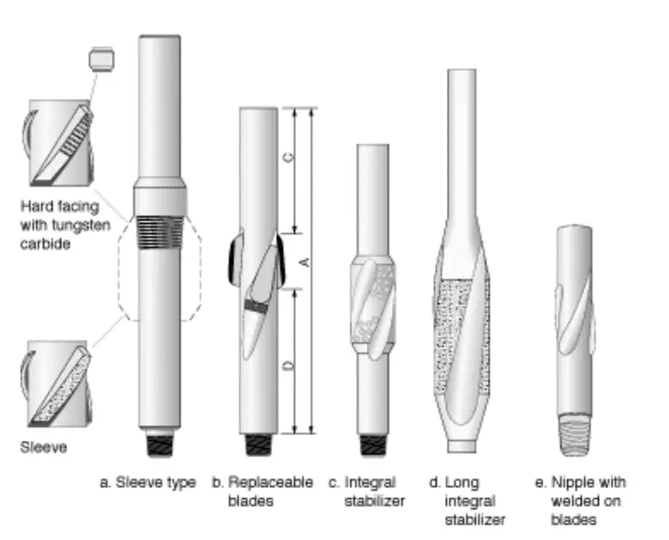
In the Drilling Stabilizer Types, Design & Application Article, we shall explain its types and applications.
Jar Placement
Jar positioning programs do exist. Most are confi gured to position Jars for maximum up Jarring effect, which is not always the desired direction of Jarring. To completely analyze Jar’s position, many factors must be considered. Usually, Jars are run in a position determined by fi eld/personal experience or company policy, and several issues should be considered when selecting the position of one or two Jars in a Drill String, including:
- Number of Jars to be run in the string.
- Likely places for pipe sticking to occur
- Most likely Jarring direction required
- Wellbore contact/differential sticking risk
- Position of Pressure Area tension =0 point (neutral point) when drilling with maximum WOB
- Depth of Hole Section
- Drag in Hole Section
- Minimum allowable measured weight for plastic buckling when not rotating
- Jar Placement inside Casing. (The Jar will most likely remain free when placed inside the casing unless sticking is inside solids, in a high-angle well where the casing is above 60 degrees.)
In the Drilling Jar Types & Placement article, we shall explain its types and best practices for its placement in drill string design.