Jetting (or badgering) technique is used in directional wells to deviate wellbores in the soft formation. The technique was developed in the mid-1950s and superseded the use of whipstocks as the primary deflection technique. Although jetting or badgering in directional drilling has subsequently been supplanted by downhole motor deflection assemblies (as the primary deflection method), it is still used frequently. It offers several advantages, which make it the preferred method in some situations.
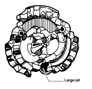
A particular jet drilling bit (like the one shown above) may be used, but it is also common practice to use a standard soft formation tricone bit, with one gigantic nozzle and two small nozzles.
Requirement For Jetting Technique
- The formations must be soft enough to be eroded by the drilling fluid emerging from the large jet nozzle. As a rough rule of thumb, formations that cannot be directional drilled at penetration rates greater than 80 ft/hr using normal drilling parameters are unsuitable for jetting or badgering. Jetting is most effective in soft, sandy formations, and of course, effectiveness is reduced as depth increases since the formations become more compacted. In the Gulf of Mexico, the maximum depth for effective jetting is approximately 2500 feet.
- Adequate rig hydraulic horsepower must be available. For jetting to be successful, adequate hydraulic energy must be available at the bit to erode the formation. A rule of thumb for jetting is that drilling fluid velocity through the large jet should be 500 ft/sec or more significant.
Jetting Assemblies In Directional Wells
A typical jetting assembly used to drill a 12 1/4″ pilot hole is:
- 12 1/4″ jet bit
- extension sub
- 12 1/4″ drilling stabilizer
- UBHO sub
- 3 x 8″ Drill Collar
- 12 1/4″ stabilizer
- Drill collar
- Heavy Weight Drill Pipe as required.
- Drill Pipe to surface
This is a strong angle build rotary BHA Type with a suitable bit for jetting or badgering in directional drilling. The upper stabilizer is optional and is often omitted.
Nozzling The Bit
There are three alternatives:
- Use a specialized jet bit with a large extended bit nozzle instead of one of the cones.
- Fit one large and two small nozzles in a conventional tri-cone bit.
- Blank off one nozzle of a conventional bit to divert the flow through the other two.
Flow through two jets may be desirable in large hole sizes (e.g., 17 1/2″) because of the large washout required to deflect the bit and near-bit stabilizer. Both (1) and (2) work well in most hole sizes which are commonly jet drilled. (2) is the most common option because it uses standard bits and nozzles and results in a bit dressed in such a way as to be suitable for jetting and drilling.
A 12 1/4″ bit dressed for jetting or badgering in directional drilling would typically have the main nozzle size 26/32″ or 28/32″ and the other two nozzles 10/32″ or 8/32″.
Jetting Technique Procedure In Drilling Directional Wells
- The assembly is run to the bottom, a survey is taken, and the large jet nozzle (the “toolface“) is orientated in the required direction.
- Maximum circulation is established (e.g., 800 GPM [3,000 L/Min] in 12 1/4″ hole), and a controlled washing away of the formation opposite the large jet is effected, with the kelly in the rotary table and the table locked.
- The drill string may be spudded up and down periodically but not rotated until several feet of hole have been made, and the bit and near-bit stabilizer have been forced into the washed-out pocket. The technique is to lift the string 5 to 10 feet (2-3 m) off the bottom and then let it fall, catching it with the brake so that the stretch of the string causes it to spud on the bottom rather than using the total weight of the string. Another technique that may improve the effectiveness of jetting involves turning the rotary table a few degrees (15°) right and left while jetting.
- Having jetted 3 to 8 feet (1-3 m) of the hole, the exact distance depending on the required build rate and previous results, drilling is begun. The circulation rate is now reduced to about 50% of that used for jetting. Hole cleaning considerations are ignored while drilling the next 10 feet (3 m). High weight on bit (40-45 Klb / 18-22 tons) and low rotary speed (60-70 RPM) should be used to bend the assembly and force it to follow through the trend established while jetting. Progress may be difficult initially because of interference between the stabilizer and the irregularly shaped jetted hole.
- After approximately 10 feet (3 m) of the hole has been drilled, the pump rate can be increased to perhaps 60% – 70% of the rate used initially while jetting in directional wells. High WOB and low RPM should be maintained. The hole is drilled down to the following survey point.
- A survey is taken to evaluate progress. If the dogleg is too severe, the section should be reamed and another survey taken.
- At the start of a kick-off, jetting is repeated every single until about 3° of angle has been built. After that, it is customary to jet every “double.” After drilling each section, the jet nozzle has to be re-orientated to the desired toolface setting before jetting again. The operation is repeated until a sufficient angle has been built and the well is heading in the desired direction.
The Principle
The principle is that a pocket is produced in the formation opposite the jet nozzle during the initial spudding and washing process. When high WOB is applied and the drill string rotated, the bit and near-bit stabilizer work their way into the pocket (the path of least resistance). The collars above the near-bit stabilizer bend and contact the low side of the hole. This causes a bending moment about the near-bit stabilizer, which acts as a pivot or fulcrum, and the bit is pushed harder into the pocket (i.e., the direction in which the large jet nozzle was initially orientated)
Advantages Of The Jetting Technique In Directional Wells
- It is a simple and cheap method of deflecting well bores in soft formations. No special equipment is needed except, perhaps, a jet bit.
- The dogleg severity can be partly controlled from the surface by varying the number of feet “jetted” each time.
- The survey tool is not far behind the bit, so survey depths are not much less than the corresponding bit depths.
- Orientation of the toolface is fairly straightforward.
- The same assembly can be used for standard rotary drilling as an angle-build assembly.
Disadvantages
- The technique only works in soft formation and usually only at shallow depths. For this reason, jetting is mainly used to kick directional wells off at shallow depths.
- In jetting, high dogleg severities are often produced. The deviation is produced in a series of sudden changes rather than smooth, continuous changes. For this reason, it is usual practice to jet drill an undergauge hole and then open it out to full gauge, which smooths off the worst doglegs.