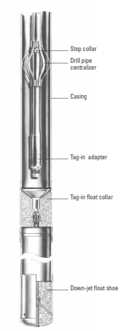
Inner string or stinger cementing is a technique typically used with large-diameter casings in which drill pipe is placed inside the casing as the conduit for pumping fluids from the surface to the casing annulus (Fig. 1). The inner strings can be run in one of three ways that will be discussed later in this article.
Cementing Stinger Operations Procedures
In general, performing the job through drill pipe can prevent many problems related to cementing (Cementing in drilling) large casings types. The stab-in technique procedure, which can only be used on stationary rigs (land rigs and jack-up rig or platform rigs), are as follows:
- The casing is run in place with a stab-in float shoe.
- The casing is set in the casing slips, thus suspending the string off the bottom.
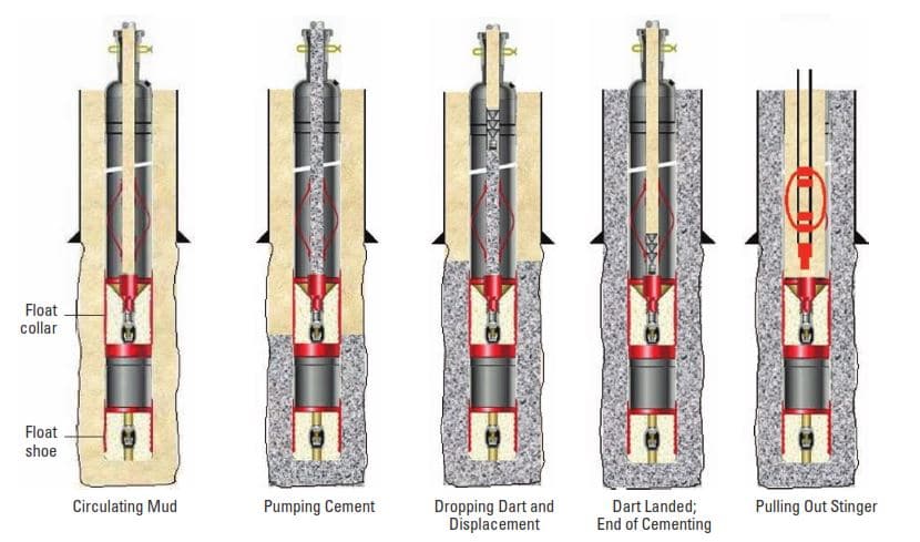
- Drill pipe made up with a stab-in stinger (Fig. 2) is then run in the casing until it is approximately 3 ft [1 m] above the float shoe.
- Circulation with the drilling fluid is then established, and returns come from the annulus between the drill pipe and the casing.
- Circulation is stopped and the drill pipe is lowered, enabling the stinger to stab or screw into and seal in the float shoe. While a constant watch is maintained on the fluid level in the casing-drill pipe annulus, which must remain stationary.
- Circulation is broken again, and one typically observes returns flowing between the conductor pipe and the casing.
- Cement is mixed and pumped through the drill pipe and up the annulus until the slurry reaches the surface.
- As soon as mud contamination is no longer evident in the cement returns, mixing can be stopped and the drill pipe volume displaced.
- Upon completion of the cementing operation, the drill pipe is rotated to the right for several turns, and the coarse threads release the stab-in tool.
Inner String Cementing Considerations
- If lost circulation is noticed before the cement reaches the surface, mixing should be stopped and the cement displaced, avoiding the pumping of large quantities of cement into the fractured zone.
- Also, care must be taken to avoid casing collapse because of excessive differential pressure between the outer annulus and the drillp ipe-casing annular space.
- Special packoff cement head assemblies can be used to seal the drill pipe-casing annulus and allow pressure to be applied. This pressure serves to offset the pump pressure that creates collapse loading whenever inner-string cementing operations are conducted. Alternatively, mud of an adequate weight can be pumped in the drill pipe-casing annulus before stabbing.
- Various options are possible with the through drill pipe stab-in technique. A backup check valve (float collar and float shoe) can be run as depicted in Fig. 2. Alternatively, a stab-in float shoe alone could be used. The types of available stab-in tools offer the possibility to latch into the float collar or shoe, thus preventing pump out of the stinger while cementing.
- Simpler stab-in tools are also commonly used that omit the latch-in design and simply rely on the drill pipe weight (API Drill pipe specs) to hold the stinger in place while cementing.
- Special drill pipe centralizers centralize the stinger and the last few joints of drill pipe, particularly in directional drilling wells.
Cementing Stinger Applications
Through drill pipe cementing has several advantages.
- Accurate hole volumes & cementing calculations (most often unknown in a conductor or surface holes) are not required, because the cement slurry is mixed and pumped until returns are observed at the surface.
- This procedure optimizes the total volume of cement mixed and pumped and virtually eliminates the possibility of over displacement because the subsequent volume displaced from the drill pipe is negligible.
- This method also eliminates the need for large-diameter swages or cement heads, as well as large casing wiper plugs.
- Also, minimal cement contamination occurs during through-drill pipe cementing.
Cementing Stinger Risks & Disadvantages
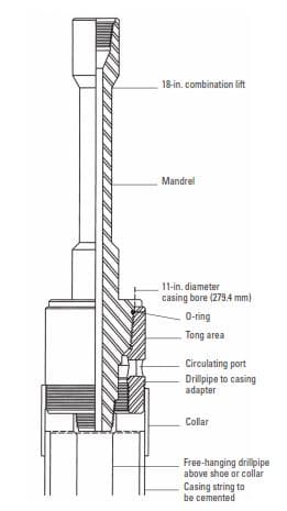
Collapsing the casing is the greatest risk in stab-in cementing operations. This may occur if the annulus becomes blocked for any reason. A preferred adaptation of through-drill pipe stab-in cementing is therefore offered by using a cementing mandrel (Fig. 3) with the drill pipe (or tubing) hanging freely to within 15 to 30 ft [4.6 to 9.2 m] of the shoe or collar. This type of arrangement, often called inner string cementing, offers the additional possibility of casing reciprocation.
In addition, unlike the stab-in technique, it can be used on a floating rig, in which the drill pipe hangs underneath the conductor (or surface casing) wellhead-housing running tool. Above all, it eliminates the possibility of casing collapse, because the pressures in the annulus and within the casing are equal. The pressure inside the casing (the drill pipe-casing annulus) can be monitored at the packoff head (on a stationary rig). However, during U-tubing, the column of fluid in the drill pipe-casing annulus is not controlled, resulting in possible cement slurry contamination.
Inner string cementing equipment
Stab-in
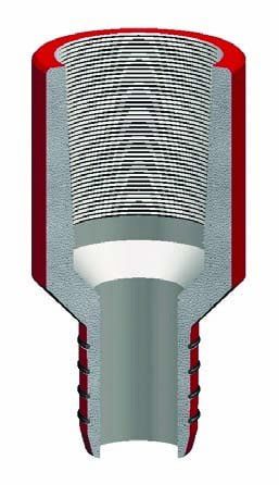
With the stab-in stinger cementing method, a simple stinger is fitted to the bottom of the drill pipe and then lowered into the receptacle (usually plastic) where a set of O-rings or special seals are engaged (Fig. 4). Once the casing reaches the desired depth, the stab-in stinger and centralizer are connected to the drill pipe and run into the casing. The drill pipe is lowered until the stinger engages the receptacle.
For stingers without a latch, additional weight must be applied to counteract the lifting force (backpressure) created while cementing. The maximum lifting force may be estimated by multiplying the maximum expected pumping pressure by the end area of the stinger, including the seals. A simple guideline is to apply 10,000 to 20,000 lbf [44.5 to 89.0 kN] to provide adequate pipe weight. One should also check for fluid coming up the annulus. If it is not sealed, then add an additional 10,000 to 20,000 lbf [44.5 to 89.0 kN]. Achieving this weight may require the use of drill collars or heavy-weight drill pipes, so this weight availability should be considered ahead of time.
The shoes and collars are basically larger versions of the types previously discussed, with the addition of a seal receptacle and beveled surface. They are available for 9 5/8-in. and larger casings, but are most often used in 18-in. and larger sizes. In some floating-rig offshore locations, the drill pipe stinger is actually suspended above a standard float collar or shoe, and the cement is pumped into the float equipment to compensate for wave motion because it represents the path of least resistance.
Stab-in receptacles on the float collar are often fitted with a latch-in plug receptacle, which differs from a latch-in stinger. Using drill pipe gives the operator a positive indication that the displacement process is complete because there is a direct observation from the surface. It also leaves behind one more seal to prevent any U-tubing of the cement back inside the casing.
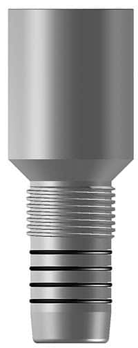
Screw-in Stinger
The screw-in stinger (Fig. 5) is also mounted on the end of the drill pipe, but the stinger has a set of coarse threads located above the seal assembly. The threads are mated to an aluminum or cast-iron receptacle on top of the float collar and can be released with about 11 turns to the left. This feature is sometimes used to run the casing like a scab casing liner (Chapter 14), but this operation is dangerous because the casing is in compression when picked up from the bottom by the drill pipe, thus reducing the collapse pressure. Most float equipment of this type is rated to about 100,000 lbf [445 kN] of pickup force, but the rating must be verified by the vendor. This version of float equipment is seldom made to be PDC drillable.
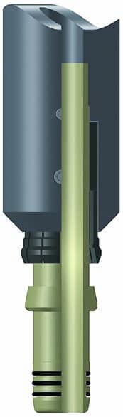
Latch-in Stinger
The latch-in cementing system is similar to the screw-in stinger, but the stinger is fitted with a split threaded ring that allows the stinger to be stabbed in (Fig. 6). The stinger must be rotated out or unscrewed to be released. Today, very few operators use the latch-in stinger because of potential release problems in the field.
Conclusion
Casing running operations are designed according to the type of valve used. The lowering speed should be slow enough to prevent surging. Float equipment may require more frequent filling to prevent collapse.
The inner string isolates the casing interior from the pumping and hydrostatic pressures created while cementing. Care should be taken to prevent creating pressure differentials that may exceed the collapse resistance of the casing. To help prevent collapse, pressure may be applied to the inside of the casing with the use of a packoff head.
The principal advantages of using stab-in stinger cementing equipment are listed below.
- Greatly reduces displacement volumes and time
- Wastes less overdisplaced cement when cementing to surface
- Decreases the need for extended-working-time cements
- Contributes less contamination because of reduced area and turbulent velocities in the drillpipe
- Is more environmentally friendly because it reduces the amount of built-up materials around the wellhead before abandonment
References:
- Well Cementing Second Edition – Erik B. Nelson and Dominique Guillot
Pop up to subscribe repeating every time I load page. I have subscribed already. Turn it off.