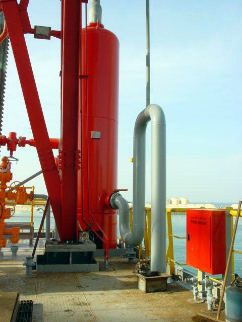
A mud gas separator, also known as a poorboy degasser or oilfield gas buster, is a critical component of drilling operations in the oil and gas industry. Its location is downstream of the choke manifold. This will make it able to separate gas from the drilling fluid. In addition, its design will assist preventing the release of toxic gases and ensuring the safety of the drilling crew and equipment.
When circulating out a gas kick in critical situations, there may be an ejection of a mixture of gas and mud from the well at high rates – as foam, gas, and slugs of more-or-less gas-free liquid in rapid (and chaotic) succession. Without efficient separation of the gas and liquid phases, we may lose a substantial quantity of mud at the surface. This may lead to suspending well-killing activities while making up fresh fluid supplies. This is a hazard to be avoided if at all possible.
Definition of Mud Gas Separator
The separator is typically a vertical vessel that utilizes baffle plates or a series of baffles to efficiently separate the gas mixture from the mud returning usable drilling mud to the active system. The gas venting will be through a vent line while the mud flows back into the tank.
The mud gas separator’s design is essential to handle the high pressures and volumes of gas encountered during the drilling hole. It will assist in controlling well kicks. Proper sizing calculations and consideration of various factors such as fluid levels, gas cutting, and separator configuration are essential in designing a MGS to ensure its effectiveness in gas separation.
Manufacture Specifications
The manufacturing process for mud gas separators is typically according to API RP 53. The dimensions of a separator are critical in that they define the volume of gas and fluid a separator can effectively handle. An example of some MGS sizing guidelines is SPE Paper No. 20430: MGS Sizing and Evaluation, G.R. MacDougall, December 199 l Drilling Rigs. The following links for different manufacturers’ specs:
building of all poorboy degasser or MGS shall be in compliance with API 12J and ASME Boiler and Pressure Vessel Code, Section VIII, Division I (latest revision). In addition, all materials shall meet the requirements of NACE Standard MR-01-75/ISO15156 (latest revision). All welding on the vessel shall meet ASME requirements. The new oilfield gas buster shall be hydrostatically tested to 190 psi to verify a maximum working pressure of 150 psi, as per ASME.
The Function of Mud Gas Separator
The separator is the primary means of removing gas from the drilling fluid. There are several advantages to removing a large percentage of the gas from drilling fluids before flowing to the degasser tank at the sand trap area and the pit room. The primary reason is to reduce the quantity of gas that may percolate from the drilling fluid in the mud pits and begin regaining the proper density. In other words, it will assist in minimizing the risk of gas cutting and other drilling-related complications.
Gas Cut In Mud & Solid Control
The gas in the drilling mud significantly impacts Solids control equipment. In most field applications, a lot misinterpret and misunderstand this situation. In general, gas cutting will blind the shaker screens and cause degradation of mud pump output to hydrocyclones and centrifuges.
Centrifuge, Desander & Desilter Relation With Gas Separation Process
Gas cutting can significantly affect centrifugal pumps. The pump’s output quickly decreases when gas accumulates in the impeller’s reduced-pressure area. In situations with low fluid head on the pump’s suction, even a tiny amount of gas in the drilling fluid can cause the pump to become gas-locked, limiting the mud flow. This gas locking will affect the functionality of the desilter and desander.
For these reasons, usage of a degasser before the solids-control feed pumps is essential once there are gases in the flowline.
Shale Shaker And Mud Gas Separation
Good oilfield gas buster performance will assist in solving the following problems:
- Gas cutting, which involves tiny gas bubbles in the drilling fluid, can cause screen blinding. To handle this problem, a degasser removes the entrained gas from the drilling fluid.
- Gas heading can cause surges in the mud flow rate from the well. These surges can exceed the screen’s ability to handle fluid flow. The surges occur due to rapid gas expansion at the surface.
- Foaming is another issue associated with gas cutting. It leaves a film of light, wet foam on the shaker screen. This foam is too light to be gravity-pulled through the screen. We may need to use shaker sprays and defoamers to break the foam.
Types Of Mud Gas Separators
There are several types of mud gas separators in the oilfield industry, each designed to efficiently separate gas from drilling mud. The most common types include closed-bottom, open-bottom, and float-type separators.
The mud/gas separation principle is the same in all types of separators. Differences between these types are mainly in the method of maintaining the mud leg. As the drilling mud enters the vessel, the gas separates due to the difference in density. The gas rises to the top (vent line) while the heavier mud settles at the bottom.
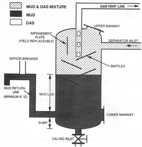
Closed Bottom Gas Buster In Oilfield
Closed-bottom mud gas separators design has a closed base that allows for the accessible collection of the separated gas. As the drilling mud enters the separator, the gas rises to the top, and then mud will move down to the BTM of the gas buster. The primary application of this separator type is where there is a large volume of gas.
The U-shaped bend in the mud return line will control the mud leg. Therefore, by adjusting this length, we adjust the fluid level.
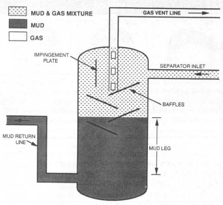
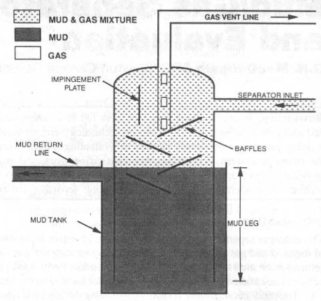
Open Bottom Gas Separator
On the other hand, an open-bottom separator or poorboy degasser has an open base. So it will be mounted on a mud tank or trip tank. In this type, we can easily control the mud leg by controlling the fluid level in the mud tank. Therefore, moving the separator up and down will control this mud leg. The primary application of the open-bottom gas separator technology is where the volume of gas is relatively low.
Float Type Separator
Float-type separators incorporate a float mechanism that helps maintain a constant liquid level within the vessel. The float rises or falls with the fluid level, ensuring a constant mud leg for effective separation. This separator type is particularly useful in drilling operations where the gas volume fluctuates. Generally, we can modify the float type to closed bottom by disconnecting the float, removing the valve, and installing a mud leg in the mud return line.
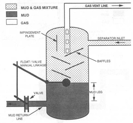
The use of float-type mud gas separators has some issues due to their design:
- The possibility of mud-return-line valves clogging with solids.
- When losing the rig air, air-operated valves stop working, and there is no control over the fluid level in the separator.
- The manual linkage had issues with the linkage failure. This will result in causing the return line valve to work incorrectly.
Summary
The float-type gas buster is not common in the oilfield due to the problems they cause. It is preferable to use a closed-bottom type instead. Open-bottom separators are acceptable, but they limit the maximum mud leg height.
In conclusion, mud/gas separators come in different types to accommodate varying gas volumes and operational requirements. Whether it’s a closed-bottom, open-bottom, or float-type separator, the mud/gas separation principle remains the same.
Mud Gas Separator Design Features
The main design features for poorboy degasser are:
- Adequate height and diameter.
- Internal baffling to aid gas break-out.
- Fluid seal by U-tube into the trip tank or dip tube.
- Gas vent outlet of adequate diameter and length.
- Liquid outlet to be large diameter
The mud/gas separator is designed to cope with a range of conditions since drilling fluid properties may vary widely, as will the characteristics and behavior of the kick fluids. The type of drilling fluid and the particular conditions existing within the wellbore will also considerably affect the environment within which the separator has to operate.
Vessel Size
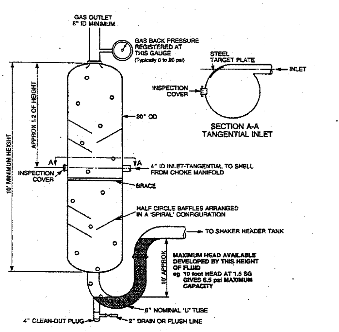
The size of the separator is critical in determining the volume of fluid and gas which MGS can safely handle. Reasonable minimum size criteria are a diameter of 48″ and a vessel height of at least 16 feet to provide sufficient capacity to handle most gas kick situations. Note that the separator inlet should have at least the same ID as the most extensive choke manifold line after the chokes. This is typically a 4″ ID, though larger sizes are often used.
We may improve the separator’s efficiency by arranging for a tangential inlet. This will help create a centrifugal action that encourages faster gas break-out. To protect the tank wall at the inlet area, a target plate should be provided to minimize erosion where the gas-liquid mixture initially contacts the oilfield gas buster wall. It will be necessary to arrange for an inspection hatch access nearby to check plate wear and carry out a replacement when needed.
The inlet should be located approximately at the tank mid-point. This permits the top half to act as a gas chamber, while the lower portion allows gas to separate in the retained fluid. As the drilling fluid and gas mixture enters, the operating pressure will be the summation of atmospheric & vent line friction back pressure. The vertical distance from the inlet to the static fluid level is intended to allow time for gas break-out on the baffles. It also increases fluid levels during the separator operation to overcome liquid outlet line friction losses.
Baffles
The interior of the poor boy degasser may be provided with a series of baffles. These thin sheets are often cut as half-diameter circles and arranged in a spiral pattern of cascades to encourage liquid gas separation. The plates should be well-braced to the vessel body.
Fluid Seal
If gas pressure in the separator overcomes the hydrostatic pressure of the fluid in the U-tube trap at the separator bottom, gas will blow through into the shale shaker room. The U-tube or liquid outlet system should be arranged to provide a minimum U-tube height of at least 10 feet. The fluid of, say, 0.52 psi/ft will support a back pressure of 5 psi. The liquid outlet line should be at least 8″ ID, although 12″ is advised to improve the handling of high-viscosity contaminated drilling fluid flows. Some drilling fluid types and well fluids combinations can produce very high viscosity and significant gelation.
Vent Line
To minimize back pressures, the derrick gas vent line should be of large diameter, with as few bends as possible. 8″ ID lines are strongly recommended. It has been common practice in the past to use thick-walled line pipes for these derrick vents. This seems unnecessary, given the pressures involved, and reduces the internal dimensions, limiting the capacity of the degasser vent line
Mud Gas Separator Consideration & Technical Requirement
Many oil and gas companies have their own policies concerning using MGS or oilfield gas buster. Below we are presenting one of the best policies in the oilfield. This policy includes the following:
- MGS or oilfield Gas buster (poorboy degasser) shall be installed on every rig.
- The mud gas separator design for ‘deep gas rigs’ is shown in Figure A-1 Minimum internal capacity for Gas Rig MGS is 35 barrels.
- The mud gas separator design for ‘oil development rigs’ is shown in Figure A-2 Minimum internal capacity for Oil Rig MGS is 17.5 barrels.
- MGS should be cleaned out periodically.
- Never circulate cement returns through MGS.
- MGS tends to shake and rattle when they are in use. They should be securely anchored.
NOTE: Pressure Relief Valves (PRV’s) are not required on the MGS.
- There should be a bypass line upstream of the separator directly to the flare line and a valve on the separator inlet line to isolate and protect the separator from high pressure.
- The mud discharge line from the separator must have a vacuum breaker stacked vent line if the discharge line outlet is lower than the bottom of the separator. This is to prevent siphoning gas from the separator to the mud pits. The vacuum breaker stack must be as high as the separator. There will be no valves installed on this line.
- We must thoroughly inspect these liquid gas separators or oilfield Gas Busters every five (5) years. This is according to API-510. Inspection will include full visual, dimensional, and 100% Magnetic Particle or Dye Penetrant NDE. We should conduct UT inspection to determine the integrity of the wall thickness. Additionally, submitting Inspection Documentation with a minimum 3-year validity is a must at the new rig acceptance or rig drilling contract renewal.
Vent Line Requirement
The vent lines must meet the following requirements:
- OIL Service: Vent Lines will be 8” minimum OD flanged or clamped steel line.
- GAS Service: Vent Lines will be 10” diverted into dual 8” OD flanged or clamped steel line at ground level.
- The minimum length of the oil and Gas vent lines will be 100’ beyond the far outside edge of the Reserve pit.
- No valves allowed.
- Same pressure and H2 S rating (or greater) than the MGS’s.
- Shall be appropriately anchored and positioned 100’ beyond the far outside edge of the reserve pits to prevent ignition of any waste hydrocarbons while circulating gas from the wellbore.
Mud Gas Separator Inspection
The rig maintenance and inspection schedule should provide for the periodic nondestructive examination of the mud gas separator to verify pressure integrity. This examination may be performed by hydrostatic, ultrasonic, or other examination methods. Generally, poorboy degasser shall be inspected per the manufacturer’s recommendations and API RP 53.
Conclusion:
By definition, we use the diverter system to divert the flow away from the rig. The oilfield gas buster, by design, is an integral part of the rig. If we direct the flow to the MGS, it would essentially go ahead to the rig. As a result, any malfunction in the MGS can and has caused considerable damage and/or loss of life. The inability of the MGS to handle high flow rates can create an extremely hazardous situation. We must understand that under certain conditions, the availability of a MGS as part of the system could be of use in circulating raw drilling fluid, which simply has a gas cut.
The primary concern with using the MGS is if the flow rate becomes excessive and is not recognized, the results could be catastrophic. Also, using a poorboy degasser requires additional valving and controls to the diverter system. Always remember that we must keep the diverter system as simple as possible. Therefore, we should not use the MGS as part of the diverter system.
References:
- SPE Paper No. 20430: Pressure Mud Gas Separator Sizing and Evaluation, G.R. MacDougall, December 1991 Drilling Rigs
- Shell Well Control Manual
- Drilling Fluid Processing Book In Oil Field