Well recompletion can bring a different reservoir interval into production through an existing well. For this change of producing zone, the design must solve two connected problems: exclude the old interval as intended and provide a usable production path from the new one. Whether the tubing can remain installed depends on the actual completion, its access restrictions and the isolation required. [1, 2]
This guide compares upward and deeper recompletion. It follows the connection from the selected reservoir to the surface, using original conceptual drawings and a hypothetical diameter example. The objective is to explain the design decision before a job program is developed.
What Does a Change of Producing Zone Involve?
An original completion may leave some reservoirs unopened or prepare them for later production. Bringing one of those intervals into service can extend the use of the well, but the new connection must be considered alongside every existing opening and isolation boundary. A new set of perforations is only part of that arrangement. [1]
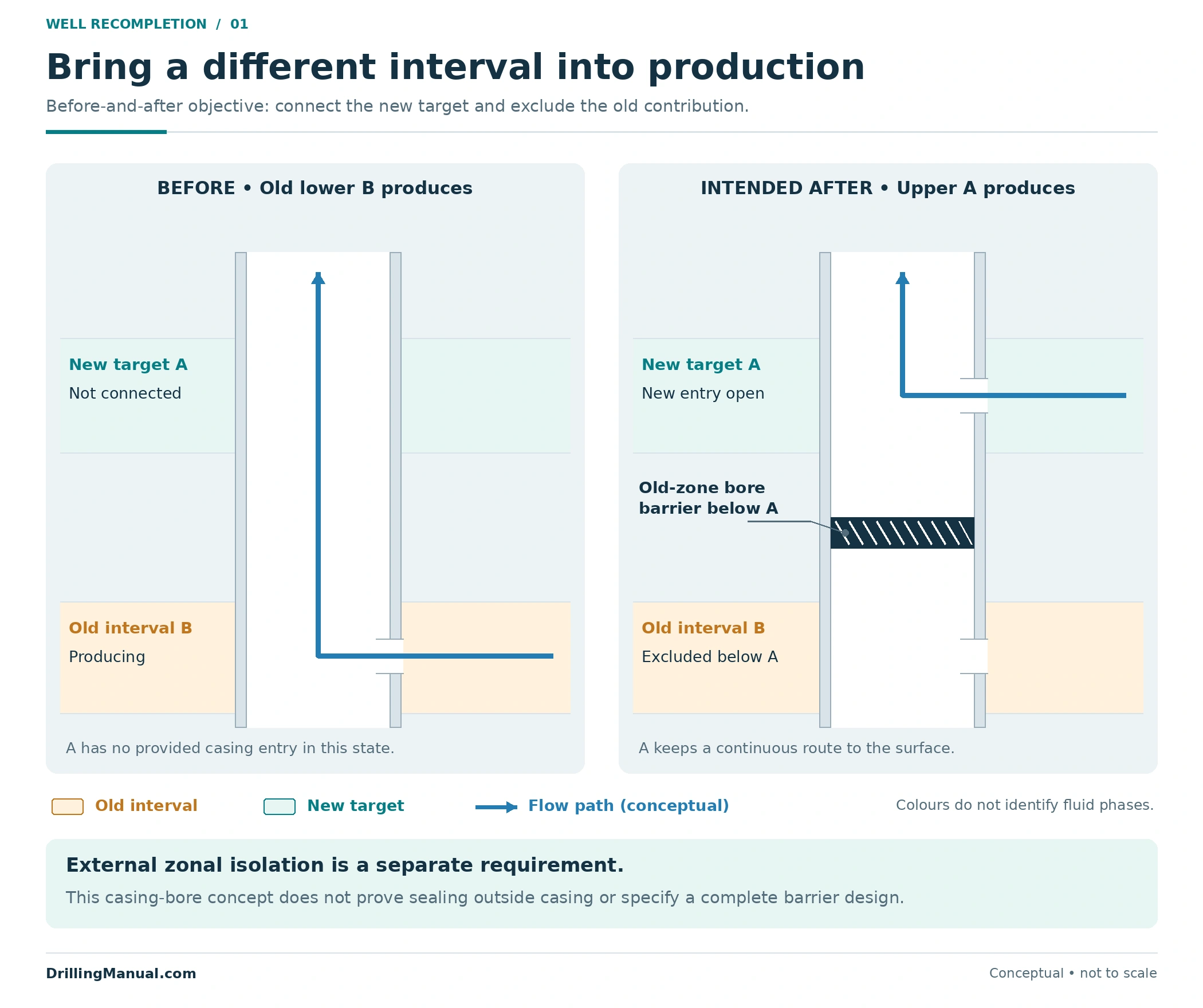
State the intended final configuration explicitly: which interval will produce, which interval will be excluded, where the new fluids will enter the completion, and how they will reach the surface. If future access to the old interval matters, include it as a design requirement. The broader workover operations guide addresses the choice between work through installed tubing and recovery of the completion. [1, 2]
| Decision | Main change being considered | Question that still needs an answer |
|---|---|---|
| Zone-change recompletion | Bring a different interval into the producing arrangement | How will the old interval be isolated while the new connection remains usable? |
| Additional perforating in the existing pay | Modify the connection to the same producing interval | Is that connection the restriction responsible for the production problem? |
| Water or gas exclusion | Reduce an unwanted contribution or communication path | Does the remedy also require a different interval to be brought into production? |
| Multiple-zone completion design | Arrange access and production control for several intervals | Which of those provisions are actually installed and usable for the proposed change? |
These objectives can occur in the same workover, but they are not interchangeable. This article concentrates on the interval change. The separate multiple-zone completion guide explains the wider architecture; same-zone stimulation and detailed perforating design remain separate decisions. [1, 2]
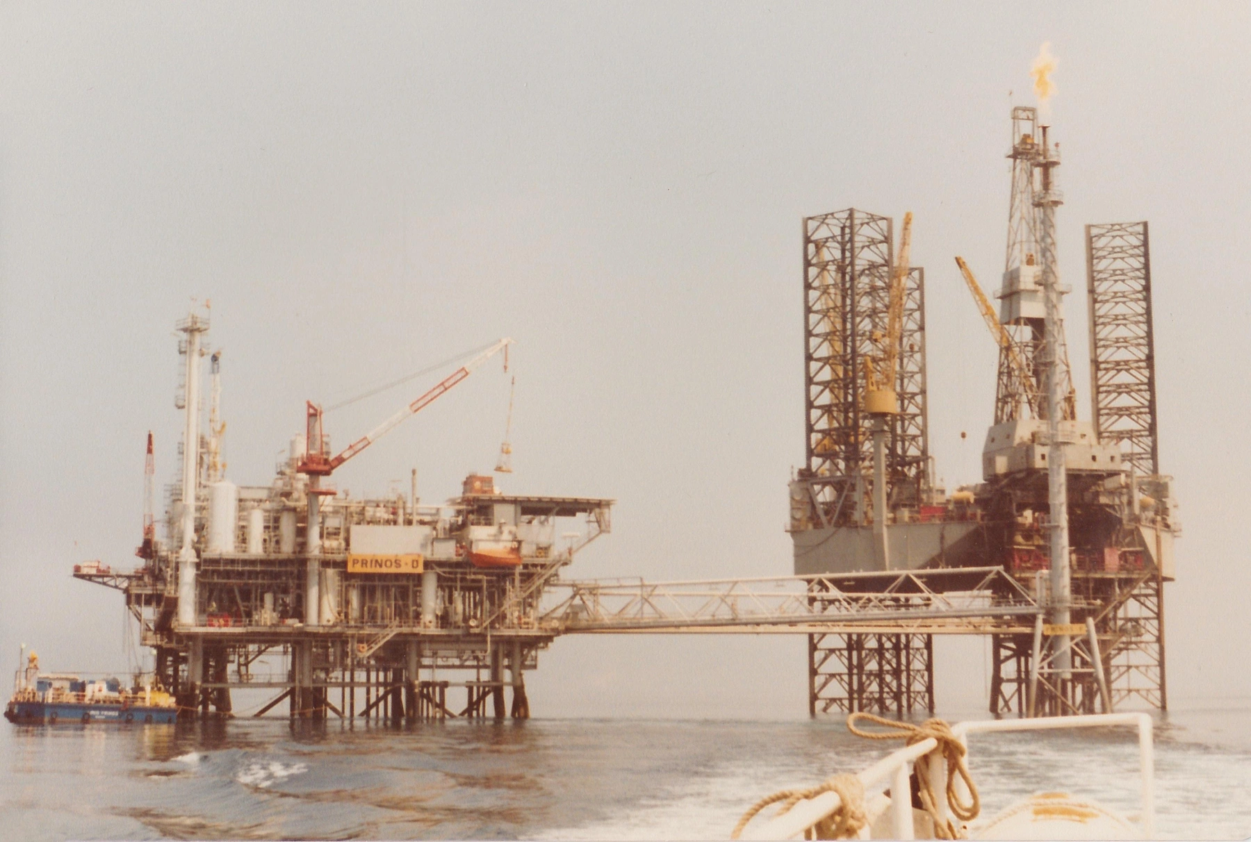
Photo: thintruman / Flickr, via Wikimedia Commons, CC BY-SA 2.0. Resized and converted from JPEG to WebP; original framing retained, with no retouching or content alteration.

Establish Where the New Target Sits in the Existing Well
Start with the reservoir target and the well as it exists today. Petroleum Well Construction relates completion selection to reservoir information, wellbore data, fluids and well-test evidence. For recompletion, those inputs must be connected to the installed equipment and the intended production conditions of the new interval. A target on a geological interpretation is not yet an established access route. [1]
Separate three positions: the new interval relative to the old pay, the new interval relative to the installed tubing and packers, and the new interval relative to the present wellbore extent. “Deeper than the old producing zone” does not necessarily mean “below the existing well.” Conversely, a deeper geological target may require additional wellbore construction before a completion connection is possible. [1, 2]
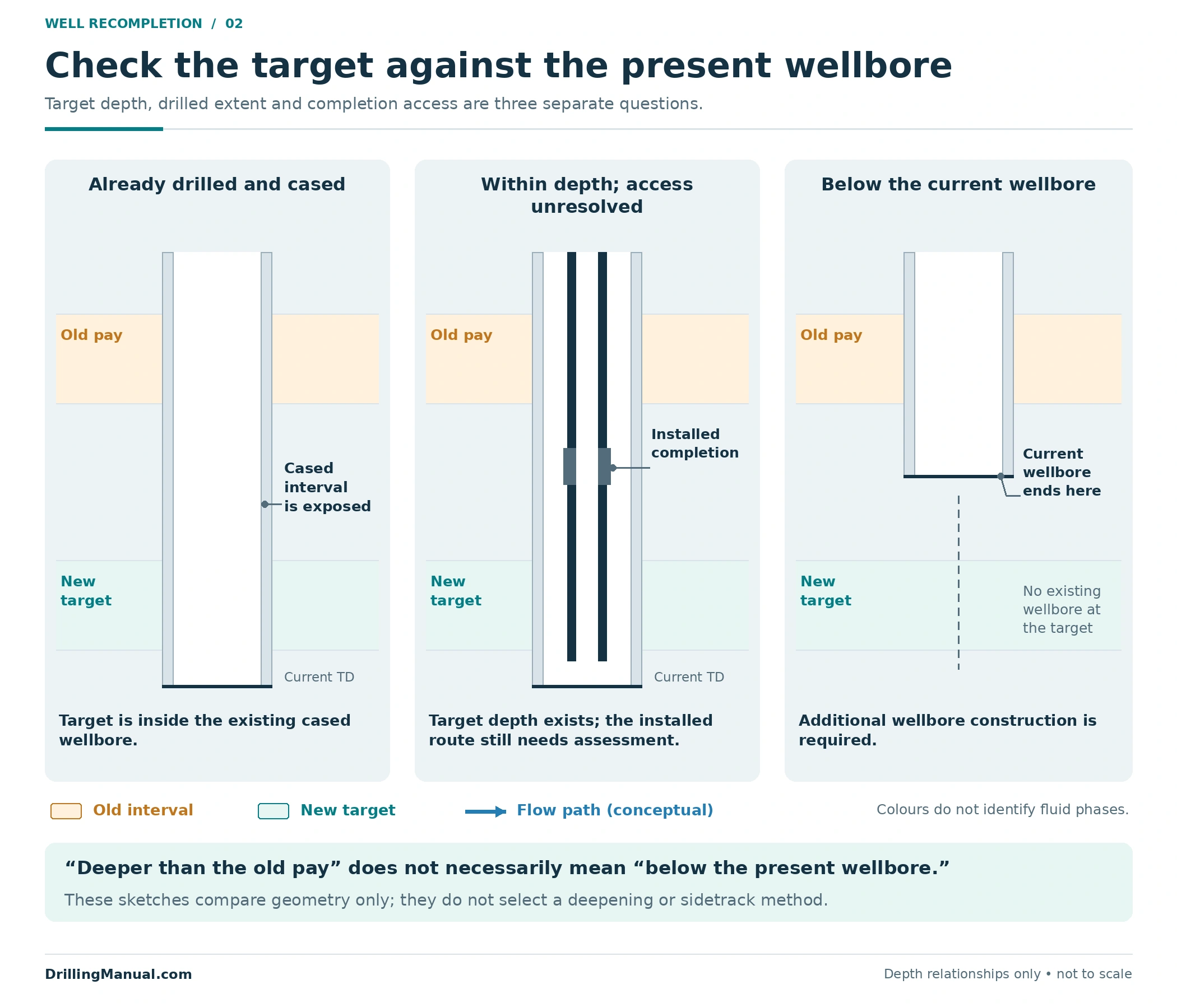
Perrin describes changing from an old producing zone to a previously unused formation, while noting that some configurations can be modified within the existing well and others may require deepening or sidetracking. That distinction must be resolved before comparing intervention equipment. New-hole construction is outside the access comparisons developed here. [2]
Record whether the target is behind casing, already perforated, behind a controllable completion connection, or outside the presently completed section. Also establish what separates it from the old interval. A cased-hole drawing with individual perforated zones cannot simply be transferred to an open-hole completion with different isolation boundaries. [1]
Upward Recompletion: Was Access to the Upper Zone Prepared?
An upper target may lie behind tubing that passes through its depth. That fact alone does not create an inlet from the formation to the production bore. The location of the packer, the casing perforations and any controllable tubing connection determine whether the interval can be brought into service while the completion remains installed. [1]
The retained-completion example in Petroleum Well Construction prepares an upper interval during the original completion: the interval is perforated and its production is controlled by a sleeve or a packer-and-tubing arrangement. This illustrates the value of planning future access. It is not a universal claim that every upper target must have been perforated originally or that every upward recompletion requires tubing recovery. [1]
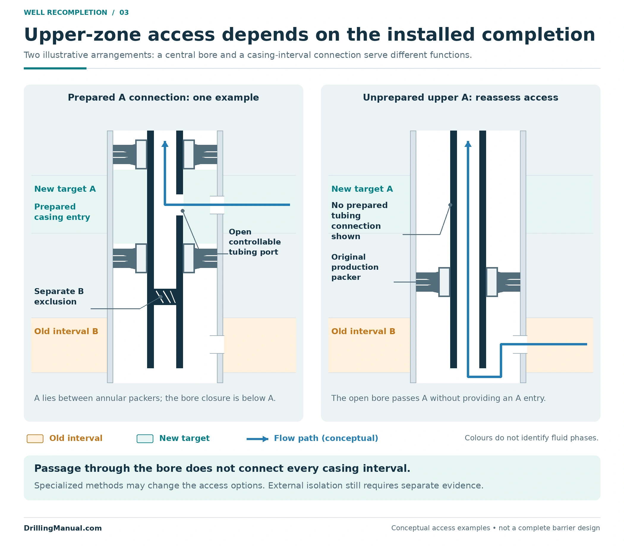
Compare two hypothetical wells with the same upper target. One has a prepared, isolated interval with a usable sliding sleeve. The other has no designed connection to that interval behind the installed tubing. Their reservoir objective is similar, but the completion changes needed to achieve it are different. A tool that can travel down the central bore does not automatically solve the second well’s missing connection. [1]
In an upward change, a closure below the new upper entry can leave that entry connected to the surface. Whether a particular closure achieves the required isolation still depends on the completion and external communication paths. Its position must be assessed against the whole final configuration, including any intended later access. [1, 2]
Deeper Recompletion: Preserve the Route Past the Old Zone
Where the deeper interval is already within a suitable existing wellbore, through-tubing perforating may provide access without removing the completion. The book presents this as a possibility, not an automatic consequence of the target being lower. The installed restrictions, conveyance route and required isolation remain decisive. [1]
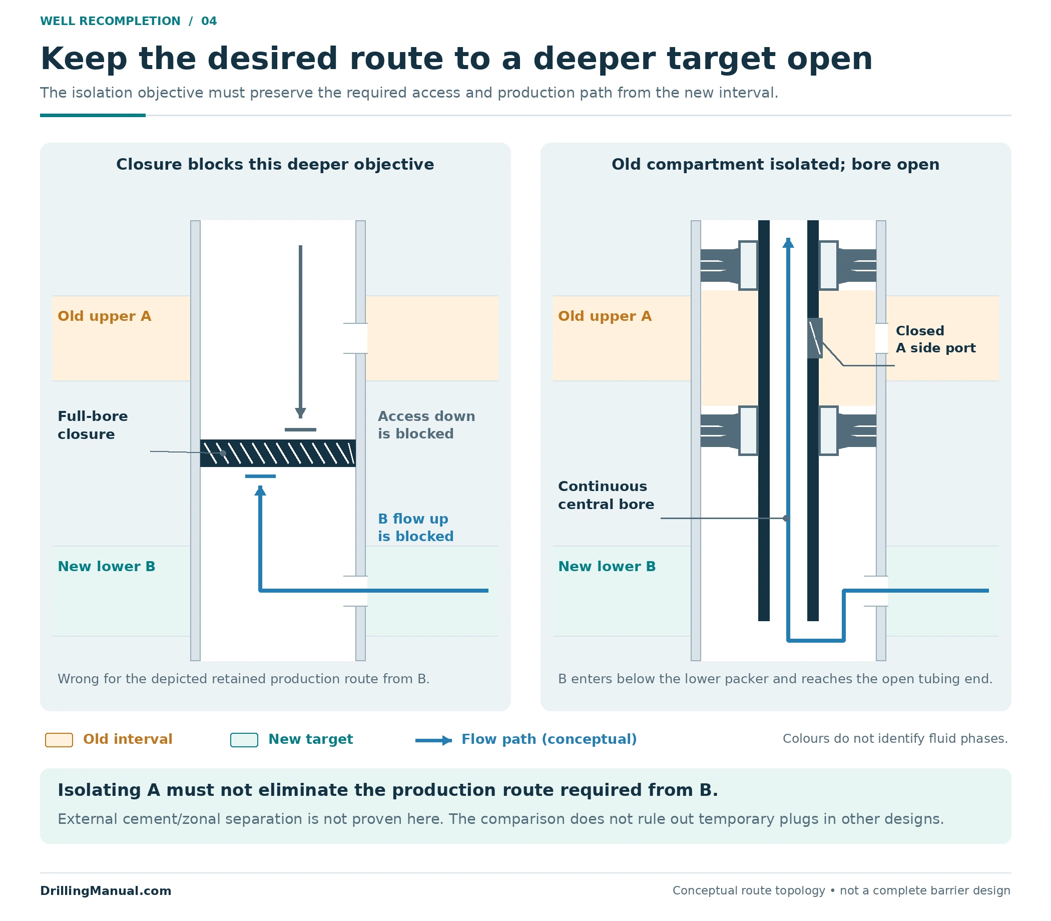
A deeper target introduces a useful geometry check: can the design exclude the old upper interval while leaving access and production from below? A solid closure across the entire bore above the deeper target would interrupt that route. An arrangement that isolates the old interval around a continuous production passage has a different function. The following drawing compares those concepts; it does not specify a field assembly. [1]
Depletion of the old interval is not a substitute for isolation. Petroleum Well Construction specifically discusses protecting shallower depleted zones from wellbore fluids during deeper recompletion. The old interval’s condition and the communication paths must therefore remain part of the design even when its current production has little value. [1]
| Design question | New target above the old interval | New target below the old interval |
|---|---|---|
| Where must the new entry connect? | Into a usable path above the old interval | Into a path that remains continuous past the old interval |
| What can a full-bore closure obstruct? | A closure below the new entry may leave its upward route available | A closure above the new entry can block both access and production from below |
| Which completion provision is critical? | A usable upper-zone connection and appropriate separation | Access to the deeper target together with isolation of the old upper interval |
| What must be checked about wellbore extent? | Whether the target and its required connection are accessible in the existing configuration | Whether the target is already within the well or requires deepening or a different wellbore path |
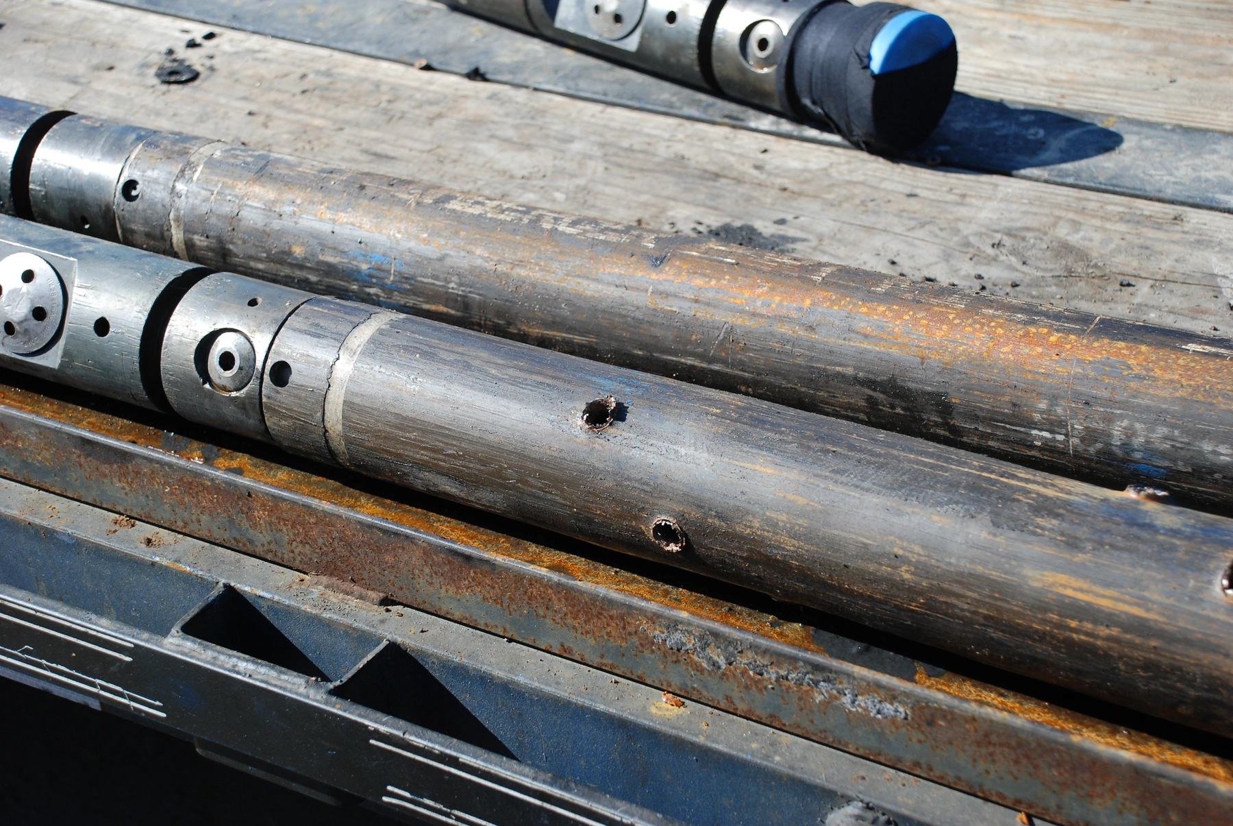
Photo: William L Cunningham / USGS, Public domain. Resized and converted from JPEG to WebP; original framing retained, with no retouching or content alteration.
The through-tubing perforating guide addresses access through an installed completion. Broader perforating methods address the reservoir connection. Neither choice, by itself, establishes that the old zone has been isolated or that the final completion is suitable for the new service. [1]
The Smallest Required Passage Controls the Diameter Screen
The nominal tubing size is an incomplete description of access. The book’s completion examples identify restrictions associated with safety-valve equipment, nipples, packer bores and tailpipe components. The route must be considered with those components in the intended access state. A large tubing bore does not cancel a smaller opening farther down the required path. [1]
Consider an original hypothetical comparison. Both layouts have an assumed clear tubing internal diameter of 68 mm and an open safety-valve passage of 60 mm. The packer passages differ. The candidate is a rigid assembly with a maximum running outside diameter of 56 mm, including its largest component. These numbers describe no commercial tool or actual well.
| Assumed clear passage or comparison | Layout A | Layout B |
|---|---|---|
| Tubing internal diameter | 68 mm | 68 mm |
| Open safety-valve passage | 60 mm | 60 mm |
| Packer passage | 52 mm | 64 mm |
| Smallest passage on this assumed route | 52 mm | 60 mm |
| Smallest passage minus 56 mm assembly diameter | −4 mm | +4 mm |
| Conclusion from this comparison alone | This rigid candidate cannot pass the assumed 52 mm opening | The candidate is not ruled out by diameter alone |
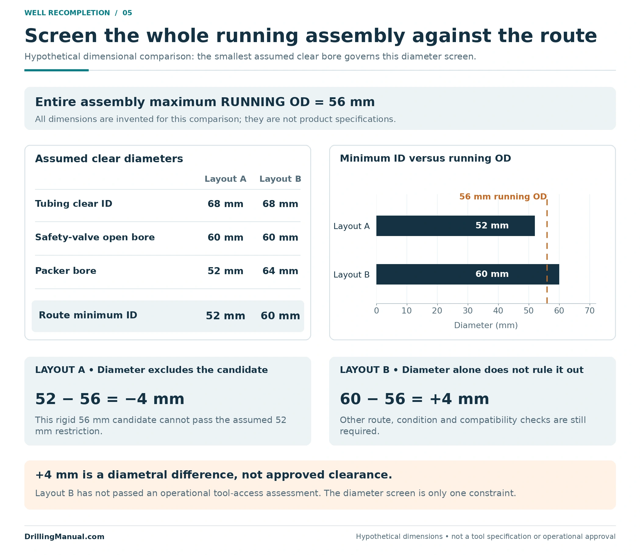
The arithmetic uses the smallest relevant clear passage, not an average of component diameters. Layout A excludes this candidate from the assumed route; it does not exclude every possible through-tubing solution. Layout B’s +4 mm is a diametral difference, not an approved operating clearance. No required clearance is proposed by this example.
A candidate that survives this screen still needs an appropriate conveyance route, verified access condition, compatibility with the well geometry and a way to perform its required function at the target. The equipment arrangement must also support the intended isolation and subsequent production. Diameter is one constraint within a completion design, not a complete intervention decision. [1, 2]
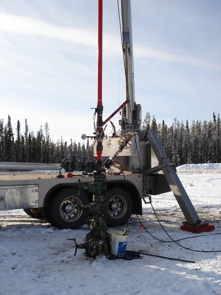
Photo: Dexcel / Wikimedia Commons, Public domain (author release). Converted from JPEG to WebP; native dimensions and original framing retained.

Choose Isolation for the Connection That Must Remain
Begin with the required isolation boundary, then assess the equipment or remedial work that can provide it. A bridge plug closing a bore, an installed sleeve controlling an inlet and a completion arrangement isolating an annular interval perform different jobs. Their suitability depends on which routes must be closed and which routes must remain available. [1]
The tubing and production packers must be assessed together. Closing a side connection is meaningful only in relation to the seals and other openings surrounding it. Likewise, bore isolation does not establish that the formations are separated outside the casing. The book’s selective-recompletion discussion explicitly depends on suitable cemented casing and liners. [1]
If the required separation calls for remedial cementing, that need may change the access and workover scope. The source describes squeeze work as likely to require completion removal in its example, while some plugback and wireline work may avoid a full tubing workover. Use this as a design dependency, not a universal equipment rule. The squeeze cementing guide covers the separate operation. [1]
Evidence about external isolation should answer the specific communication question. A completion sketch cannot establish cement condition. The cement bond log guide provides related evaluation background; the recompletion proposal still has to identify what separation is required and how its condition will be established. [1, 2]
When Can the Tubing Stay, and When Might It Need Recovery?
Retaining the tubing is a candidate when the necessary target access, isolation and new production connection can all be achieved within the installed arrangement. Recovery becomes a candidate when that arrangement prevents an essential part of the work, when equipment must be replaced, or when the required recompletion design differs materially from what is installed. The choice follows the functional requirements. [1, 2]
Compare three outcomes. A prepared upper zone may have a usable controlled inlet. A deeper interval may be accessible through an open bore if the old zone can be isolated without obstructing it. Another well may need its completion recovered to provide the required access or configuration. The phrases “upward” and “deeper” identify target position; neither phrase decides the service method on its own. [1]
Recovery planning also depends on what is attached to the string and how the packer interfaces work. A design using a permanent packer and seal assembly has different service implications from one using a retrievable packer. Establish which components would remain and which must be recovered before calling the proposed work a simple tubing change. [1]
Check the New Zone Against the Rest of the Completion
The ability to reach an interval is not the same as a completion suitable for producing it. The design must account for the intended reservoir and fluid conditions, tubular strength and materials, packer and seal interfaces, production performance and the servicing provisions that will remain after the change. These are linked requirements. [1]
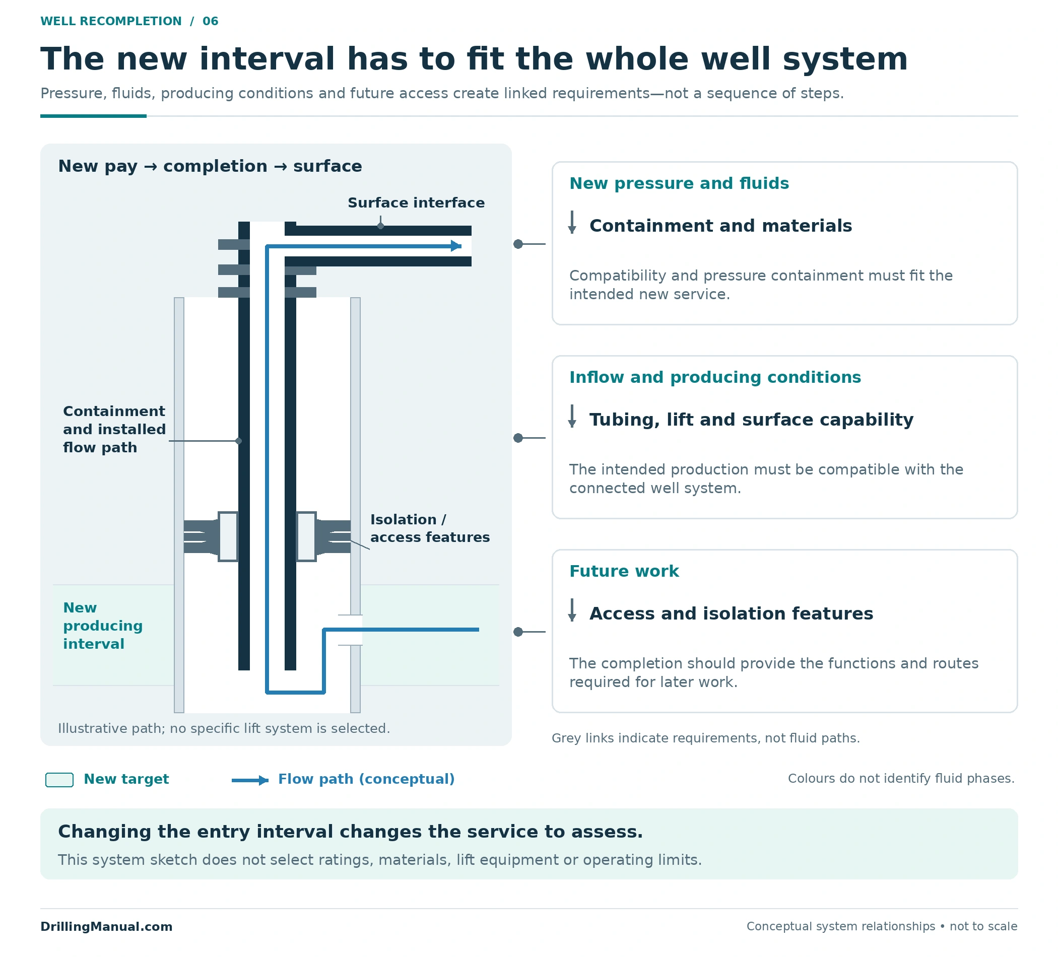
For example, changing the expected fluids can change the material assessment, while a different inflow and production regime can change tubing or artificial-lift needs. Perrin treats modifications to production conditions separately from restoration or alteration of the formation-to-wellbore connection. A recompletion proposal should address both where they interact. [1, 2]
Future work also matters. A configuration that produces the new interval may constrain later logging, isolation, treatment or another interval change. Record those consequences when comparing retained-completion and recovered-completion options. The benefit of a larger or more continuous passage depends on the functions the well will actually need. [1]
Build a Recompletion Brief Around Six Questions
The following is an original review framework assembled from the books’ completion requirements and intervention distinctions. It organizes the evidence needed for a decision; it is not an operating sequence or a prescribed acceptance checklist. [1, 2]
- What is the new target? Define its location, supporting reservoir information and relationship to the existing wellbore extent.
- What happens to the old interval? State the intended exclusion, remaining communication and any later re-entry requirement.
- What access actually exists? Describe the installed completion, relevant restrictions and usable connections in their intended states.
- Where must isolation act? Separate the wellbore boundary from external zonal separation, and identify any remedial work needed.
- What new service must the well support? Assess the new pressure, fluid, production and equipment requirements together.
- What evidence will demonstrate the result? Define the required final functions, production assessment and future-access record.

Verify the Intended Functions Separately
Completion of the intervention does not answer every performance question. Evaluate the final arrangement against its stated functions: the old interval’s exclusion, the new interval’s connection, the required containment and service functions, and the production response. The categories below are an editorial application of functional-requirement design, not a list of universal field tests. [1, 2]
| Required result | Evidence question | Conclusion to avoid |
|---|---|---|
| Old interval excluded as intended | Does the evidence cover the relevant boundary and remaining communication paths? | A completed equipment movement proves every old-zone path is closed |
| New interval connected and contributing | Is the intended connection established, with a production response attributable to the new arrangement? | A new opening alone guarantees useful production |
| Required containment and well functions retained | Are the applicable functions demonstrated for the final configuration under the well program? | A favorable production rate proves all integrity functions |
| Production objective assessed | Are the rates, fluids and operating conditions recorded and compared with the intended outcome? | A single rate describes long-term performance or every interval contribution |
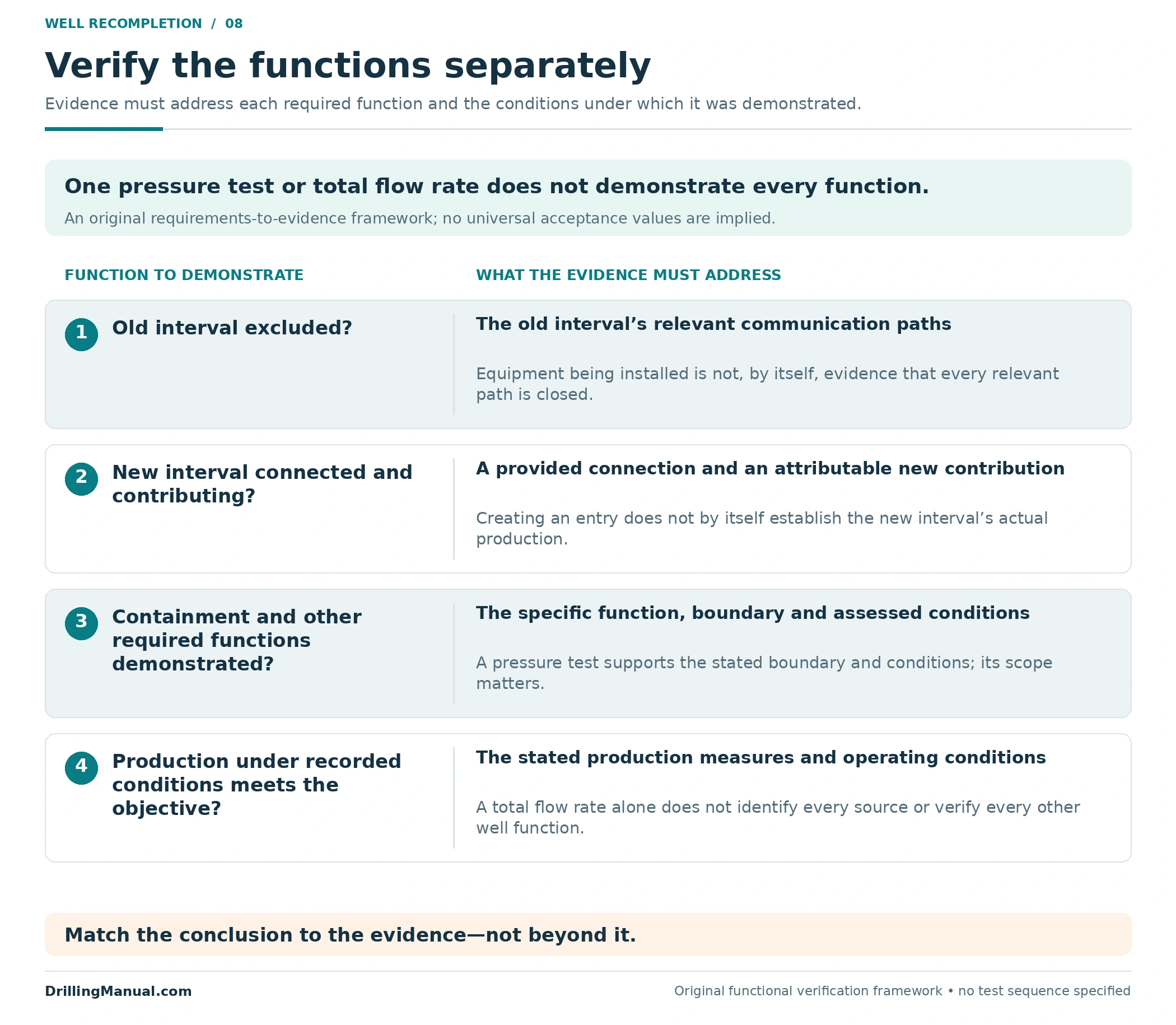
The final records should make the new completion configuration understandable to the next intervention team. Keep the distinction between a production result and evidence of the required well functions. The well integrity guide addresses that broader management context. Actual verification methods and acceptance criteria belong in the applicable well program. [1, 2]
Well Recompletion: Frequently Asked Questions
Is Recompletion the Same as a Workover?
A workover can address equipment failure, production conditions or the reservoir connection. The zone-change recompletion discussed here has a specific objective: bring a different interval into the producing arrangement. Its access requirements determine whether the completion must be recovered. [1, 2]
Does Well Recompletion Always Require Pulling the Tubing?
No. The source describes recompletion opportunities through retained tubing and examples requiring a full tubing workover. The decisive issue is whether the installed arrangement can support all necessary access, isolation and production functions. [1]
Can an Upper Zone Be Opened Through the Existing Completion?
It can be a candidate where the completion provides suitable access and a controlled connection. A prepared sleeve or selective arrangement is different from an upper target with no usable connection behind installed tubing. The actual design must be established first. [1]
Does a Deeper Recompletion Always Involve More Drilling?
No. A target below the old producing interval may already be within the existing well. A target beyond the present wellbore may instead require deepening or sidetracking. Target position and existing wellbore extent are separate facts. [1, 2]
Can a Bridge Plug Above the New Zone Prevent the Recompletion?
A full-bore closure above a deeper target blocks the continuous route through that bore. The design must place or select isolation so that the required new-zone connection remains available. That geometry question precedes selection of a particular device. [1]
Does a Tool Smaller Than the Tubing ID Have Sufficient Access?
Not necessarily. Another component may have a smaller relevant passage. The hypothetical 56 mm assembly cannot pass Layout A’s assumed 52 mm packer opening, despite the 68 mm tubing ID. A favorable diameter comparison also leaves other deployment and functional checks unresolved.
How Does This Differ From Reperforating the Same Zone?
Additional perforating can modify the existing pay connection. A change to a different interval also requires decisions about the old zone, the new production path and the final completion. Perforating may be one element of that larger change. [1, 2]
Does Flow From the New Zone Prove the Recompletion Succeeded?
It provides production evidence, but the full result also depends on the intended old-zone exclusion, the required well functions and performance under documented conditions. Assess those requirements separately; one favorable observation cannot establish every function. [1, 2]
Technical References
[1] Dunn-Norman, Shari, and Clark Robison. “Designing Well Completions for the Life of the Field,” Chapter 18 in Petroleum Well Construction, edited by Michael J. Economides, Larry T. Watters and Shari Dunn-Norman; John Wiley & Sons. Consulted 903-page educational digital copy, especially physical/visible pp. 864, 869–875 and 889–895. Used for functional requirements, future-zone access, upward and deeper recompletion, installed restrictions, servicing implications and interactions between completion components. Historical field dimensions, operating values and technology statements are not adopted as present equipment limits or universal procedures.
[2] Perrin, Denis, with Michel Caron and Georges Gaillot. Well Completion and Servicing. Editions Technip, English edition, 1999. Chapter 5, especially printed pp. 255–257 / physical PDF pp. 267–269. Used for access and production evidence, workover objectives, changes to the producing connection and the distinction between work within an existing well and possible deepening or sidetracking.
Engineering explanations come from these supplied books. The comparison tables, hypothetical diameter calculation, review framework and drawings are original educational constructions. Photograph sources, context and reuse information appear in their captions.