Cement Design & Programming for primary cementing operations of any type of casings / Casing liner requires the following input:
- Size and depth of the hole.
- Well Trajectory (Inclination).
- Possible mud circulation loss zones encountered.
- Gauge and shape of the well-bore.
- Hole contents and drilling fluid properties (gradient, rheology and whether OBM or an aqueous fluid).
- Pressure regime in the well-bore.
- Top of cement.
- Casing size and weight (and/or ID).
Although there are several placement techniques that can be used in primary cementing (Cementing in drilling), they have a number of features in common. Therefore and for the sake of simplicity, we discuss the most straightforward single-stage operation in detail. Where appropriate mention will be made of special features applicable to other technique(s).
Hole and mud conditioning
When casing seat depth is reached consider the costs/risks benefits of a check trip. At this time mud conditioning, to achieve a homogeneous fluid in the hole for running casing can be included.
Calliper
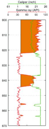
The logging program should include the running of a caliper tool to get the best possible actual gauge of the hole for volumetric calculations. Although in cost-benefit terms a one-arm caliper log from, the PDC/CNL may suffice; a four-arm calliper logging tool combined with an integrating facility is highly recommended to get the most accurate reading on the hole volume. The (higher) costs for the integrator tool will be (partly) offset by reducing excess cement costs which otherwise are incurred. After logging a further check-trip (check also: Tripping Pipe procedures) may be considered to ensure that the hole is stable and ready for casing running operations.
Casing configuration In Cementing job Design
Although the design of the casing string to be run falls outside the scope of this article, a number of elements have a bearing on the cementing process and its ultimate results (cementing tools). It is, therefore, appropriate to discuss features that have an impact on the cementing operation in this article
Guide or float shoe
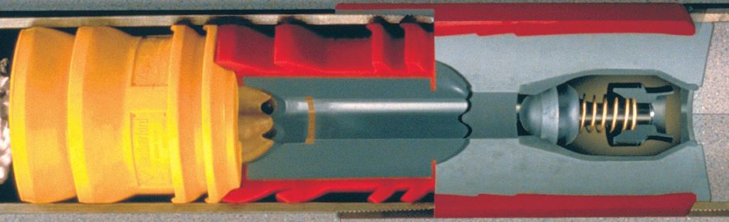
In the choice of this item, fluid passage and permissible flow rate are important considerations, given the fact that the fastest possible rate is a prerequisite for optimum displacement efficiency. This may preclude the use of an automatic fill-up or differential valve construction which does place a limit on pumping rate to avoid premature tripping. Also, possible fouling of the shoe bore by the bottom fill of the hole when landing the casing should be taken into account. The results of the Gast) check before running casing will provide evidence of this and therefore should be heeded. Lastly, when drill-out of the shoe track is required or possible in the future for the next hole section, drillability must be ensured.
Float collars
Prevention of back-flow after displacement and sealing the top plug are of great importance to avoid having to drill out a large cement column inside the casing. Also, the integrity of the cement around the shoe may be compromised by backflow. Installation of a reliable check valve, able to withstand the rigors of abrasion and erosion during mud circulation, pumping, and displacement of cement, is therefore necessary. As a further precaution, it may warrant the consideration of installing a collar backed up by a float shoe.
Stage / port collars
The use of stage equipment will complicate, even may preclude, the use of top and bottom plugs in cementing the lower stage(s). It also will place a limit on the displacement rate/pressure in order to avoid the premature operation of the stage collar. It follows from this that the minimum number of stages, commensurate with hole requirements, should be incorporated in the string design.
The location of collars is geared to the depth of the weak formation or loss zone that needs to be protected from excessively high hydrostatic pressures.
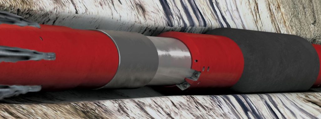
Casing externals
The Casing Centralizers, scratchers, ECPs, etc. all will contribute to a better cementing job. However, they also may impede running the string into the well-bore, particularly in highly deviated or corrugated holes with washouts and ledges where the implements may hang up. This consideration will tend to put a limit on the number of gadgets that can be attached. A trade-off between these conflicting arguments must be found. Torque and drag software, such as DRD’s ‘Wellplan for Windows’, can be used to model torque and drag forces when running casing and/or liners. The coefficient of friction may be adjusted to reflect the use of casing externals.
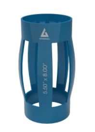
In highly deviated or horizontal holes, where the casing tends to sag to the lower side of the well-bore, installation of sufficient centralizers is mandatory, most certainly over the reservoir and other permeable sections. The location and spacing of these devices can be determined best by using a computer program that is now available with most Service Companies in oil and gas or SIPM Casing Manual (EP 92-2000). Hole rugosity and location of wash-outs are important input parameters for these programs. It obviously does not make much sense to position a centralizer in the middle of a large washed-out section with a diameter larger than the span of the (bow-spring) device. The program calculates the spacing for a given type of centralizing in relation to the requisite ‘stand-off (the minimum distance pipe to wall divided by the difference in radius of hole and casing outside). Several points need to be considered in designing the centralizer configuration, particularly in deviated holes:
Location of the neutral point between tension and compression of the string and its effect on the stand-off. The part of the casing in tension tends to be pulled to the upper side, whereas compression results in the string lying against the lower side.
Soft formations or mud cake tendency for burying the centralizers, impeding movement.
String ‘floating’ phenomena in deviated holes, an account of density differentials of fluids in casing and annulus. The forces generated by this phenomenon may exceed the starting and restoring forces of bow spring centralizers, necessitating fitting fixed types.
Differential sticking risks opposite permeable sections with a thick mud filter cake. In production liner cementing proper centralization is even more important than for a casing due to the small annular clearance between pipe and open hole, bearing in mind that the hole section to be lined is likely to be more to gauge than the larger sizes.
In operations where mud has been used which leaves relatively thick mud cakes across permeable sections, scratchers will aid in reducing cake thickness thereby decreasing the possibility of differential sticking of the casing while being run. There are no set rules for the number and spacing of scratchers to be installed. It is usually left to the Service Company to advise on this. In oversized and corrugated holes scratchers may do more harm than good and therefore should be left out.
In stage cementing installation of cementing baskets or external casing packers (ECPs) in conjunction with stage or port collars needs to be designed. ECPs provide, when fully inflated, a better seal than the cementing baskets. However the former is less reliable in operation than the baskets. It is therefore very much a matter of track record which device to program and install.
Cement head and plugs Design
Top and bottom wiper plugs are recommended for primary cementations, string configuration permitting. For operational convenience, a multi-plug Cement Head, with an appropriate fluid connection and diversion arrangement, is much preferred. When only one plug can be used it is recommended to place this at the top as this will enable detection of cement arrival at the shoe. A larger spacer should be considered to compensate for the absence of the bottom plug, countering the increased risk of cement contamination. Omitting the bottom wiper plug may also have another drawback. This is the accumulation of wiped mud ahead of the top plug contaminating the top of cement which ends up around the shoe track. This in all probability will result in a poor cement quality in this location, a weak point in subsequent drilling, and a pressure leak off test. To avoid this happening it is recommended to place the float one or two joints above the shoe to accommodate the poor-quality tail cement inside the casing.
The dual plug recommendation also stands in liner and sub-sea cementations, although it is recognized that the operation becomes more complicated and thus more vulnerable. Also, the cementing manifold attached to the top of the running (drill) string usually does not accommodate two plugs, although heads with one wiper plug plus a ball retainer, to engage the bottom plug installed in the top of the liner, are available. On the other hand contamination of cement may have a much more dire effect on liner cementation in view of the relatively lower volume of cement required for these jobs compared to casings.
Cement Volumetrics Design
The first step of the design program is to calculate the fluid volumes needed for the cement job.
The hole volume can be computed from the calliper log. If this log also integrates the volume of a hole that is corrugated and/or exhibits a non-circular cross-section a fairly accurate reading of the volume is obtained.
For callipers, without an integration facility the hole volume is calculated by sections with a uniform diameter. In some cases, the hole volume is traced from the log with a planimeter, rather than ‘eye-balling’ the average diameter section by section.
Displacement, capacity, and internal diameter of the casing/liner are read from the appropriate tables for the given casing size and weight, available from the industry.
Top of Cement And Contact Time
Where to place the top of cement is dictated by a number of factors, such as:
- Safety and containment.
- Sealing off unwanted gas and/or liquid flow.
- Hydrostatic pressures and formation strength or fracturing pressure.
- Presence of loss-zones.
- Economics.
- Protection against corrosion.
- Possible side-tracking and re-completion later.
- Desired contact time.
- For subsea producers, leak off of excessive annular pressure due to temperature differential effects.
The weighing of these factors, which often are in conflict, requires good judgment by the Drilling Engineer responsible for the compilation of the Cementing design program, guided by the individual OpCo practices and procedures, and good geological and well management data.
Top of Cement
As a general rule surface casings are cemented to surface (or seabed in an offshore operation), intermediate and production casings to 200 m inside the previous string, and liners up to the hanger. For long casing strings, this criteria would lead to excessive cement usage and hydrostatic pressures exceeding formation strength. In these cases, a compromise has to be found, often in the form of placing the cement top 200 m above the highest fluid or gas-bearing interval.
Contact Time In Cementing Design
Displacement and mud-cake reduction efficiency are determined by the contact time, Le. the time of exposure to the shear energy from the flowing fluid. It is generally accepted that a contact time of 10 minutes or longer is conducive to good displacement, leading to better cement jobs. In case the length of casing to be cemented is too short to afford a 10 minutes contact time it should be considered to use a scavenger slurry ahead of the neat cement formulation.
Spacers and preflushes
To separate cement from the annular fluid it is highly recommended to pump a spacer ahead of the cement. The nature of this spacer is dictated by the type of fluid present in the annulus.
When an oil-based mud (OBM) has been used to drill the hole section two spacers are required, the first one being a volume of base oil, followed by water. Both spacers should contain a strong non-ionic surfactant to enhance their cleaning action and effect a return to a water-wetted condition of the pipe surface.
In the case of water-based mud (WBM) a single water spacer is usually sufficient.
Spacer size(s) recommended are 5 m3 (or> 150 m in annulus) with 1%v surfactant in the case of OBM. In some cases, mostly where high mud gradients have been used, it is a practice to weigh the spacer to a gradient between that of the drilling fluid and cement slurry. As weighting the spacer has other implications, e.g. on its rheology and resultant ECD contribution, the need for this should be carefully considered. In practice, it has been shown that un-weighted spacers usually suffice.
Pre-flushes are employed to enhance cleaning out the annulus and improve sweeping drilling fluid and mud cake from the bore. They are commercially available from the service industry, offering a large range of different formulations. As pre-flushes are sometimes credited with an almost magic functionality and performance based on model experiments, these claims should be considered with sound scepticism. Practical experience has shown that pumping a cheap, larger water spacer or scavenger slurry (see below) rather than an expensive proprietary formulation, has the same effect.
Notes:
1) When planning cementation the effect of spacers and pre-flushes needs to be carefully considered with due regard to well control. Ensure that sufficient overbalance will be applied to the formation at all times during circulation, displacement, and circulating-out in case of problems developing.
2) The ‘Wellplan for Windows’ mentioned above provides the engineer with a tool to achieve and maintain well control in cementing.
Scavenger Cement Slurries Design
Scavenger cement slurries are’ diluted’ ordinary formulations, composed in such a way that no setting will occur. They are applied to extend the contact time of cement slurry under flowing conditions to enhance drilling fluid and mud cake sweep and reduce channeling of neat cement bodies. The use of scavenger slurries is highly recommended in situations where short casing (or liner) strings are to be cemented or for stage cementing operations. In the latter case, it should be recognized that after each stage the scavenger should be circulated out before commencing the next.
Cement Slurries Design
The detailed design of the cement slurry will be the subject of the cement properties and characteristics that have a place in the cementing program and thus will be discussed below.
Cement Slurry Gradient Design
The gradient of the cement slurry needs to be designed & programmed to satisfy two main requirements: pressure control and the ability for the cement to reach the desired level (TOC). This implies that the gradient should be adjusted between pore and fracture pressure. The pressure regime in the various sections to be covered thus needs to be taken into account.
A further argument to be considered is the U-tubing effect on down-hole (annular) velocities. In many cases where neat cement slurries are pumped the rate of moving down is higher than the cementing unit can supply, creating effectively a vacuum during the pumping stage. When the gradient differential is large the displacement fluid may only catch up when the cement has already rounded the shoe at an essentially uncontrolled rate. Choking the annular flow may be necessary to limit this adverse effect but could result in unacceptably high dynamic pressures down-hole.
The cement slurry gradient design can be adjusted within limits imposed by the type of cement and additives that can be used. Neat Portland cement can be made up into a stable slurry with a gradient in the range of 17 to 20 kPa/m (0.75-0.88 psi/ft). An admixture of 2% bwoc of bentonite to Oil-well Cement will allow gradients as low as 14.5 kPa/m, the same as for a Pozzolan cement. The use of fillers such as diatomaceous earth permits slurries of 12.5 kPa/m, albeit at the expense of cement strength.
In Foam cementing gradients as low as 8 kPa/m can be achieved, but the operation is much more complicated than a conventional one using Portland or Pozzolan cement.
The route to follow in formulating cement of the desired gradient is largely determined by practical and logistical considerations.
In some operations, it is common practice to design the neat main cement body with a tail-out of e.g. 100 sacks of a denser slurry to ensure high shoe strength.
Rheology
The rheology of the cement slurry has a significant impact on the equivalent circulation density (ECD) of the flowing fluid. A high ECD may put a limit on the displacement rate and consequently may lead to reduced efficiency and less optimum cementing results. In general, a cement slurry with a low’ rheology is preferred, more so as it will enable to attain turbulent conditions at lower flow rates. Standard Oil-well cement slurries have relatively high rheology as indicated by a high Consistency Index from the Power Law.
To adjust the rheology to the desired level would require the use of additives to disperse the cement particles and ‘thin’ the slurry. Most dispersants also tend to retard the setting of the cement and reduce ultimate strength to some extent. This has to be accounted for in the slurry design.
Thickening Time
There is a high time-dependent cost element in rig operations, so cementing should be completed in the shortest possible time. Short thickening times thus would contribute to keeping the cementing operation within acceptable limits. In the design for the cement job, the desired thickening time is calculated from the mixing, pumping, and displacement of a given volume of (neat) cement slurry. For contingencies, an hour is frequently added to the total of the other time elements to give the thickening time requirement.
Strength, Temperature Effects
In most circumstances, cement (all Classes) develops sufficient strength when setting to serve its main purposes of casing support, zonal isolation and pressure containment.
In high pressure/high-temperature drilling, however, the strength of ordinary Oil-well cement may not be adequate and a formulation that will develop additional strength must be programmed & designed. Low-temperature conditions will retard the development of strength. In those cases, the program needs to call for the use of specially adapted cement.
Displacement Fluid Gradient
In most cementing operations drilling fluid is used to displace the cement slurry, generally having a lower gradient. The pressure differential will cause a compression of the pipe while the cement is setting. Replacing the casing content in subsequent operation by a fluid with a lower gradient, e.g. completion brine, may cause the casing to contract even further resulting in detaching the cement from the casing and creation of a micro annulus. This effect should be taken into account as it may lead to communication and pressure transmission to the wellhead or a leaking liner lap.
Pipe Movement
It has been shown in model tests and numerous field applications that pipe movement during mud circulation, pumping, and displacement of cement, has a beneficial effect on mud (and -cake) removal and reduction or elimination of channeling. Movement of pipe during pumping and displacement is therefore strongly recommended, even considered as the default case.
- Reciprocation is probably the most straightforward and most effective way of movement in single-stage Primary casing Cementing. For liners however it may interfere with properly engaging the mechanical set liner hanger / Hydraulic set liner hanger and therefore reciprocation is only practiced during circulation, if at all. This movement also carries the risk of differentially sticking of pipe, particularly in highly deviated holes, due to more intensive contact between pipe and mud cake, key-seating, and tension/compression effects. Using a shorter stroke length will reduce this risk.
- Pipe rotation may be programmed as an alternative for reciprocation offering a lower risk of sticking. However, the number and shape of pipe attachments will be an impediment to this type of movement. If rotation of a liner is programmed a special hanger tool is required to allow for this.
In spite of the generally beneficial effects in many operations a great reluctance is perceived to move the pipe during circulation and subsequent cement displacement, more so for liners than for casing strings to surface. Most of the arguments against liner movement stem from misconceptions such as:
- Excessive drag caused by centralizers and other external fittings. This possibly may have been noticed from the hook load record when running the liner. The stroke and speed of reciprocation can be adjusted to take this into account.
- A larger/stronger drill string is required for fear of pipe parting or twisting off due to movement. It is recognised that movement adds to the pulling forces when moving up, but this incremental load is usually well within the limits of a standard 5-inch drill pipe. A hole in poor condition, with large wash-outs, severe ledges and doglegs does not lend itself to reciprocation. Rotation however is still possible.
- Swabbing and surging the pay zone due to reciprocation. This already happens when running the liner at excessive speed. Again, by modeling using Wellplan and adjusting the reciprocation rate this effect can be reduced to an acceptable level.
- Movement may adversely affect hole stability, possibly leading to bridging, making it impossible to move the liner down to its landing point. The same would happen when the pipe becomes differentially stuck (check also free point calculation for stuck pipe) in the upstroke. The latter is unlikely when the string is adequately centralized. It is recognized though that some borehole instability may be induced by these centralizers but formation material dislodged is likely to be carried up by the fluid flow in the annulus and not accumulate to an extent of forming a solid bridge.
- Fear of not being able to unlatch from the liner after cementing. It is considered that the forces causing the latching mechanism to jam are much higher in liner running than generate during carefully designed reciprocation.
Although the above arguments are brought to bear against casing string reciprocation too, these can be countered with careful design in the same way as for liners.
Pipe movement should be applied by default, whenever possible. The choice of which movement to the program is largely governed by local experience, hole condition, and quality and engineering expertise.
Computer Simulation In Cementing Design
In the programming and design of a cement job, computing plays an increasingly important role, particularly in complex cementing operations where fluids of varying density need to be pumped. The pressure regime inside the casing and in the annulus are important parameters that should be assessed in the design stage to prevent problems associated with excessive pressures in the process.
Alternative Cementing
When considering the requirements for the main cement slurry in the design alternative techniques may offer advantages over the use of Oil-well cement. Reducing waste has become a major consideration in some operations. The use of Slag-Mix under these circumstances may be profitable as it does contribute to waste reduction at no extra costs, indeed sometimes at reduced costs. The disadvantages of the Slag-Mix technology should be weighed against its benefits to decide whether to adopt this technique for cementing casing and liners.
The use of fiber cement may be appropriate in cases where high losses are incurred and cement can not be placed at the desired level by other means. A further step in the application of fiber cement is the use of the formulation to line the bore-hole. In this developing technology, a sheath of cement is placed in the annulus of a glass-fiber liner. After curing the liner is drilled out.
Conditioning Mud and Circulation
After running and landing casing and prior to the cement job proper the design program should call for the conditioning of drilling fluid in the hole. This is required to ensure that the fluid in the well-bore is homogeneous and has the desired rheological characteristics, particularly low gel strength, as well as low fluid loss to avoid thick mud cakes. Mud conditioning is done by circulation of the drilling fluid, with the cementing head without plug(s) in place, until properties in and out are the same. It will also contribute to the cleaning of the annulus and ‘mobilizing’ gelled mud.
Next in the program is the circulation at step-wise increasing rates, recording stand-pipe pressures. This design program item is aimed at the establishment of the maximum loss-free displacement rate that can be applied in the actual cementing job.
Cementing Mixing and Pumping Design
The program needs to specify the requisite volumes and quantities of all the ingredients for the various fluid parcels that are to be mixed and pumped, to be available on-site. In case additives are dissolved/dispersed in the mix water this has to be specified in the program.
The rate of mixing slurries depends largely on the cement unit configuration and may vary between 0.75 and 2.0 m3/min (5 and 12 bbls/min). The faster the mixing can be done the smaller the’ empty casing’ effect, referring to the cement in the casing falling faster than the mixing unit can supply, creating a (part) vacuum. This implies that after mixing has been completed and the switch has been made to the rig pumps for displacement the cement first has to catch up by filling the void in the casing. To avoid this situation and thereby to extend the time at optimum displacement rate it could be considered to put backpressure on the annulus through a choke ( Check also: Choke Manifold) to balance pressures inside the casing and in the annulus. The effect this has on the integrity of weak formations and potential loss zones obviously need to be considered.
The estimated time to prepare spacer, pre-flush or scavenger, chemical washes, and main cement, and the order of mixing are to be stated in the program, also calling for the actual times to be recorded. The mixing and pumping order of the various fluids usually is spacer < pre-flush < chemical wash (or scavenger) < main slurry + tail-out < after-flush < displacement fluid (mud or brine).
The first plug is launched when the spacer front is at the cement head, providing a physical separation from the preceding mud or just ahead of the (scavenger) cement slurry, while the top plug is launched between neat cement slurry and after-flush (if used).
Cement Displacement Design
When the final formulation (main slurry or the tail-out has been mixed and pumped into the casing a switch to the displacement mode has to be made. In many cases, the cementing program calls for displacement with the mud pumps, as they afford a higher rate than delivered by the cement unit pumps. It is strongly recommended to design displacement at the highest possible loss-free rate as this offers the best chance of achieving adequate mud removal and successful cementation. For safety reasons the pumps are slowed down sometime before completion or when stand-pipe pressure reaches a set limit, whichever comes first. Slowing down pumps is usually enacted some 5 minutes before the calculated displacement time to avoid the large pressure surge that would be experienced if the top plug were allowed to hit the bottom one at full rate.
Towards the end of chasing cement, the stand-pipe pressure will rise, culminating in the ‘bump’, the very steep pressure increase which signals the arrival of the top plug and seating in the bottom one.
The cementing program should include a record of pumping/displacement rate and pressures vs. time as well as a pressure test of the casing. This test is to be carried out immediately after displacement has been completed, up to the rated pressure of the plug system, before the cement thickens to avoid the formation of a micro-annulus.
Post-job programme
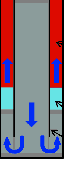
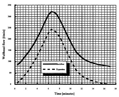
Back-flow
The design program should specify the length of time pressure is to be maintained inside the casing before bleeding off, accompanied by a check on back-flow. Some back-flow will always occur, particularly in cementing long strings in areas with high-temperature gradients, due to thermal expansion of the casing contents. This must be distinguished from back-flow due to the failure of float equipment. Thermal expansion will initially increase before falling back to zero, whereas a persistent flow signals float failure. In the latter case, remedial action may be required. (Figure 1 refers)
Close-in timing
The minimum time the casing is left standing to allow the setting and strength development of the cement is derived from the thickening. time and compressive strength testing and may vary between 8 and as much as 24 hours. Including both 8-hour and 24-hour strength measurements in the testing program enables limiting the waiting of cement time to the minimum required to reach the prescribed strength.
Evaluation
It is recommended to program for an assessment of the top of cement (Cement Evaluation) where this is a critical parameter, by temperature logging at an appropriate time after finishing displacement. This technique relies on the exothermic cement hydration reaction, causing a shift in the temperature gradient recorded by the logging tool. The earliest time this log can be run is after the establishment of thermal equilibrium in the mud column inside the casing and should be carried out before the hydration heat is dissipated. The time window to carry out temperature logging depends on a number of factors and conditions, but generally speaking, covers 8 to 12 hours after displacement has been completed.
Ref : Cementing Operations & Design Manual By W.J. van Beest