Guns normally run on wireline or tubing can also be run using coiled tubing allowing through tubing perforating to be carried out in horizontal wells. An electrical wireline can be installed inside the coiled tubing to allow depth correlation with casing collars or a gamma ray and the use of electrically initiated detonators. Here, we will discuss coiled tubing perforation in detail, including its application, limitations, and operations.
Combination Of Wireline & CT
A large number of coiled tubing logging and perforating runs have now been successfully completed, and these are now considered routine operations. To avoid the necessity of rigging up the coiled tubing injection head on top of a lubricator, the current procedure for rigging up long tools with surface CT pressure control equipment uses a wireline lubricator and cable to connect the tool string, which is then lowered into the well and hung off on a BOP, which seals against the tool.
The wireline and lubricator are then removed, and the coiled tubing containing a wireline cable is connected to the tool. The injector head is then installed, and the tool is lowered to the required depth in the well. This procedure requires that the detonator be connected ballistically to the gun assembly before the connection of the cable head. Normal perforating procedures require the detonator to be connected electrically to the wireline cable before being attached ballistically to the gun so that if stray voltages are present, the detonator alone will fire, without initiating detonation of the gun. Stray voltages present could cause the gun to detonate when the cable is connected. The use of SAFE or EBW detonators is therefore required.
Applications
- Perforating in Underbalanced Conditions: Underbalanced Perforation allows increased flow from the formation, which helps clean the perforations and helps reduce near-wellbore damage.
- High Angle/ Horizontal Well Perforating: Coiled tubing conveyed perforating could be deployed in horizontal portions of the well where conventional perforating methods are impractical or impossible.
- Coiled Tubing Used as the Production String: The coiled tubing that conveys the perforating guns can also be used as the production tubing after well completion.
Limitation
Coiled tubing applications are limited in the depth they can achieve. When the coiled tubing is required to “push” the guns down the well, the coiled tubing begins to buckle. At some point, the coiled tubing becomes locked due to helical buckling. Service companies have models of this behavior that take account of the wellbore geometry and can predict the start of this behavior.
Coiled Tubing Conveyed Perforating BHA
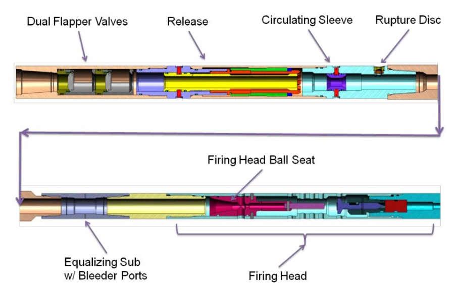
A standard coiled-tubing BHA consists of:
- Coil Connector
- Dual flapper check valves DFCV
- Hydraulic disconnect mechanism
- Circulating sub, with rupture disc
- Equalizer sub with pressure bleed ports,
- “Ball Drop Type” firing head
- Perforating gun
Coil Connector
This piece of equipment is designed to connect a tool string to the end of a coiled tubing. It provides a strong and sealed connection to the coiled tubing when installed correctly. The fishing neck (Fishing in Drilling) uses O-ring seals to maintain pressure integrity for the tool string. This particular type of connection is known as the CS-Hydril thread.
Dual Flapper Check Valve
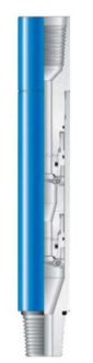
The Back Pressure Valve is a valve used in CTU operations, which is placed directly below the coiled tubing connector, and in snubbing operations, it is placed at the top of the bottom hole assembly. Its main function is to prevent the wellbore pressure from entering the work string. The valve is designed as a flapper, allowing flow down the tubing while stopping any flow coming back up the tubing. It has two flappers, and the flapper seals are an essential valve component.
Hydraulic Disconnect
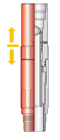
The hydraulic disconnect is a mechanism that releases the tubing from other downhole tools that are run below. It is activated by ball and tubing pressure and serves as an emergency safety joint. This mechanism is commonly used for running, setting, and releasing mechanical well packers, bridge plugs, and tubing hangers from coiled tubing.
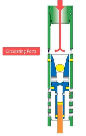
Circulating Sub with Rupture Disk
This tool creates a path for fluid circulation from the tubing to the annulus. It is ball-actuated and usually installed below the hydraulic disconnect and the downhole motor. To activate it, a ball is pumped through the tool, which shifts the piston sleeve, thus opening the circulation ports (the number of shear pins and rating determine how many ports will be exposed). A rupture disk is also included as a safety feature: if the bottom hole assembly gets plugged, increased pressure from the surface will rupture the disk, allowing circulation of the actuation ball. The rupture disk can withstand pressures of up to 5,000 PSI.
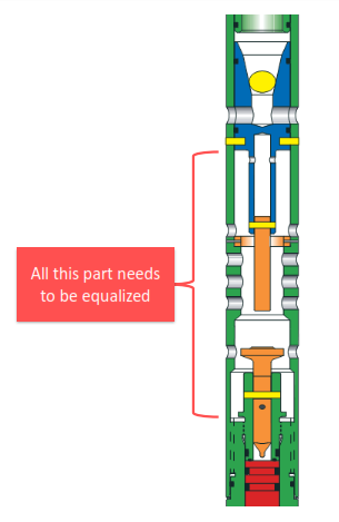
Equalizer Sub with Pressure Bleed Ports,
Normally, the vent is too small, which can cause pressure to build up against the ball seat and eventually shear it. However, if the gun did not fire after dropping the firing ball and had to be pulled out of the hole (POH) to the surface without firing, then there will be trapped pressure inside the coil. The ball seat can shear at any time due to this trapped pressure. This is where the vent comes in handy – it slowly vents the trapped pressure to prevent any misfires on the surface.
Firing Head For Coiled Tubing Perforation
The Hydraulic-Actuator Firing (HAF) Head is a tool that helps fill the tubing string automatically while running it in the well. The tool is pressure-balanced. A stainless steel or ceramic ball is either dropped from the surface, circulated downhole, and positioned inside the tool. The HAF is actuated by applying pressure to the tubing string. A stainless steel or ceramic ball is dropped from the surface or circulated downhole into the hammer piston to operate the tool.
Applying pressure to the tubing string shears the retaining pins and forces the hammer piston into the firing pin. The firing pin detonates the initiator, which starts the detonation of the perforating assembly. Circulation is regained as soon as the firing pin has been sheared.
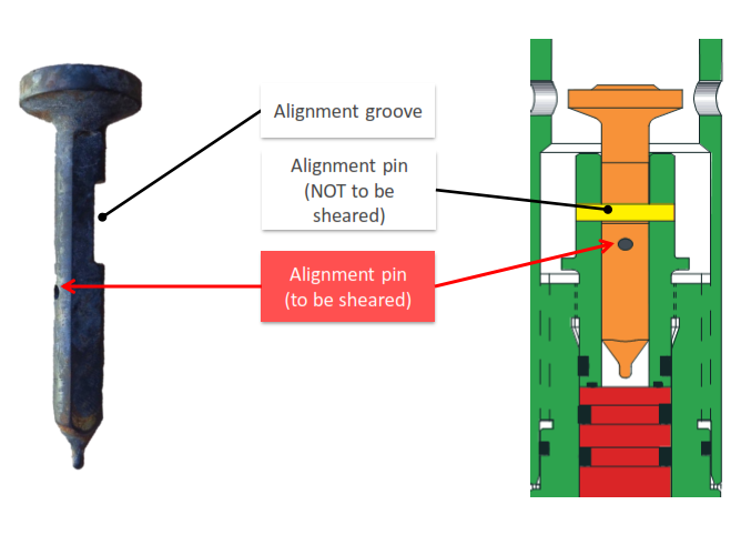
Relief ports are small openings located between the hammer and the firing pin of a firearm. They serve to equalize pressure in the area, preventing any trapped pressure from slowing down the hammer. If the firing power is not transmitted completely to the firing pin, it may not have enough force to shear the firing pin, leading to a misfire.
After firing, the ball seat moves down, reopening the circulating ports and restoring circulation. This is the most reliable indication of a successful shot.
Operations For Coiled Tubing Perforation
To secure the gun, use Nylon slings and two long tag lines and lift it towards RF. Then, make up a 2″ safety clamp below the dummy firing head in the specified place as per the operator’s instructions. Install an air tagger wire below the safety clamp and start the pick-up assembly inside the V door with a tandem lifting technique. This requires a lifting plan, one banksman, clear communication between the driller and crane operator to get the assembly in a vertical position using the air tagger.
Land it smoothly on the CT flange & Remove the wire sling. Don’t forget to change the ring gasket of CTU flange before landing the gun.
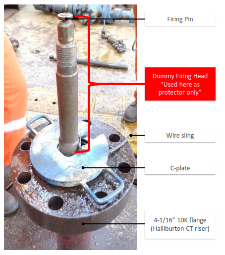
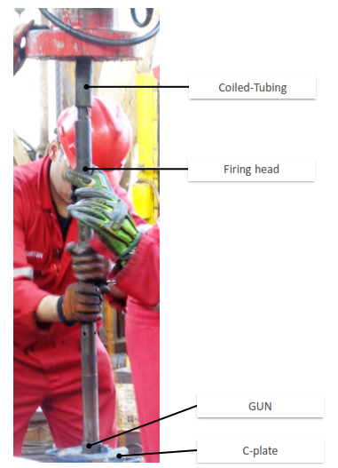
To properly install the firing head, you need to remove and replace the dummy firing head with the active one. Once installed, use a pipe wrench to connect it to the coil and PU gun assembly. Secure the connection by releasing the safety clamp and closing the CT flange. Before pressure testing the drilling riser, make sure to only test it to plate number 1 for 10 minutes to avoid accidentally shearing the ball seat. After this initial test, it should be safe to pressure test the riser to the desired value. Once the test is complete and successful, you can open the swab, LMV, and wing manual valves. To open the UMV, SSSV, and wing valves, use a hand pump.
Dummy Run
To run the dummy string, follow these steps:
- Pick up the dummy string, as previously explained.
- Conduct pressure tests as usual.
- Wash down the well with a minimum rate of 0.5 BPM (or the rate for plate number 1, whichever comes first) until the tag bottom (60 feet per minute). Observe the return and confirm the well is full through the sample point.
- Correlate the coil depth according to the last run with GR–CCL.
- POH (pull out of hole) to the surface at a rate of 70 feet per minute with a pump out rate of at least 0.5 bpm.
Firing
- L/D Dummy Run assy.
- Flush coil with 5/8” ceramic ball.
- PU & MU Casing gun assy. #1 as explained before.
- Pressure test pump lines/reel/hook up connection against tree swab valve to 500 psi for 10 min with water, bleed off to zero (500 Psi only to avoid accidentally activating the firing head)
- Pressure test DFCV to 500 psi for 10 min, bleed off to zero, open tree swab valve and LMV.
- Wash down the W/ min rate (0.5 BPM, 500 Psi, which comes first, 40 fpm max, monitor pressure) till gun is in depth.
- Confirm gun in depth / check flag marks / set core GR/CCL correlation and string under tension
- Record wellhead pressure and PU WT before firing.
- Confirm circulation-free before dropping the ball.
- Drop 5/8” ceramic ball from coil Tbg reel port.
- Pump ball with maximum 500 Psi until land ball in place.
- Raise pressure on stages to 3000 psi to activate the firing head and monitor firing indications.
- POH while pumping out to surface (0.5 BPM, 40 fpm max, monitor pressure & confirm full return) .
- Confirm BHA above the tree. Close tree vertical valves.
- Bleed off pressure in the riser to zero (on 100 psi stages, coil tbg pressure must be monitored to ensure it is also being bleed off simultaneously with the riser pressure).
- Disconnect BOP and confirm whether the gun is 100% fired or not.
- L/D TCP live gun assy #1.
- In Case the pressure in the CT does not bleed off simultaneously with the riser
- The guns must be run back to perforating depth, and the CT pressure must be increased until circulation is regained, either by the guns firing or bursting the rupture disc in the motor head assembly.
- Once circulation has regained, a ball should be pumped down to open the circulating sleeve in the motor assembly to increase the flow area before starting out of the hole.
- If it becomes necessary to run back to the bottom and circulation cannot be established between CT and annulus, the operation should be halted until a path forward is agreed upon by the customer and Halliburton management. TCP Global advisor should be contacted immediately.
Firing Indications For Coiled Tubing Perforation:
- Sudden pressure drop from 3000 psi to normal circulating pressure.
- Instantaneous change in WT on martin decker.
- Instantaneous increase in wellhead pressure.
- Return will stop when ball in place, then back again once firing where ball opened circulating path again.
- Possible sound indication.
- Possible oil in return.
Safety Precautions for POOH With Coiled Tubing Perforation Guns:
- Circulation between the CT and annulus must be established and verified by TCP Eng. And CT supervisor.
- While POOH and every 1000 ft. the coil must be stopped and circulation between the CT and the annulus must be re-established and verified.
- At 200 ft below surface, circulation between the CT and the annulus must be re-established and verified.
- When guns reached at surface in the riser and after closing the x-mass tree, all personal should be cleared from within a 100 ft. radius from riser.
- To ensure there is no trapped pressure above firing head, the coil pressure should be bleed off through the annulus. Begin bleeding the pressure in riser off slowly in increments of 100 psi. the CT pressure must be monitored to ensure it is also being bleed off simultaneously with the riser pressure.
References
- Best Practices for Hydraulic Actuator Firing Head Global Distribution Rev IADC
- Halliburton Perforating_Solutions_catalog
- coiled tubing- admarine 2
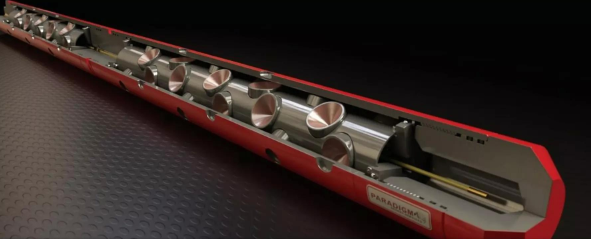
- PARADIGM® INDUSTRIES
- Coiled Tubing Perforation Case Study, AYAMAN RASHAD, WSL – KAMEL ELSAYED, WSDE, GULF OF SUEZ PETROLEUM Co. GUPCO