Drilling with a Bi Center drill bit resembles a conventional PDC drill bit. Still, specific steps must be undertaken to prepare and operate the Bi Center drilling bit properly.
First and foremost is the preplanning of the well with all concerned parties. Depending on the application, this can involve numerous service company personnel with the Operator. Items of importance are:
- Hydraulic Properties (See Also Our Drilling Hydraulics Guide )
- Lithology
- Length/depth of Interval
- Directional objectives
- Drilling Fluids
- Drill String Stabilization / Bottom Hole Assembly Components
- Casing design/objectives
- Drilling modes – Bottom hole Assembly Types – Positive Displacement Motor (PDM) – Non-rotary Steerable System – Rotary Steerable System
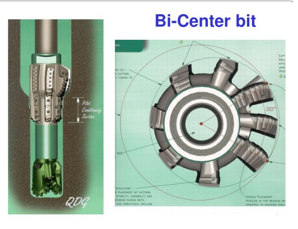
- An understanding of how the Bi Center operates and enlarges the wellbore
These items must be discussed and agreed upon before applying a Bi Center drill bit downhole.
Preparation In Job site
Steps Before Making Up Bi Center Drill Bits
- Hydraulic calculations must be performed to optimize the Bi Center performance.
- The bottom-hole assembly must be agreed upon with well objectives. This is especially important when drilling with a PDM.
- Previous bits must be inspected for gage wear, broken teeth, or junk damage (See also Our Bit grading Guide). If any previous bit is under gage, then a reaming operation trip (also check: Tripping pipe procedures) must be made to ensure a full gage hole. Reaming with a Bi Center bit is not advisable due to the design characteristics of the Bi Center drill bit.
Making Up the Bi Center Drill Bit
- The rig floorhands will handle the Bi Center drill bit, similar to a conventional PDC drill bit. Under no circumstances should the Bi Center drill bit be placed on the steel floor. Use a wooden pad or rubber mat. Damage to the PDC cutters could hinder performance if placed on the metal floor. Also, see SPE/IADC paper no. 16144 for bit handling and operation.
- Locate the bit breaker and attach it to the Bi Center drill bit. Engage the latch on the bit breaker and carefully lower the Bi Center drill bit with the bit breaker into the rotary table. Try to avoid any contact of the PDC cutters with the rotary table. Position the bit breaker so that the open end of the breaker is opposite the make-up line.
- Clean and dope the pin (Thread Compound).
- Lower the drill string to the top of the pin and engage the threads.
- Make up the bit to the recommended torque of the drill collars directly above the bit.
- Remove bit breaker and carefully lower the bit, and drill the string through the rotary table.
- Guide the bit and drill string through the blowout preventers and wellhead. The bit should not take any weight or be obstructed in any way.
- Trip slowly through casing shoes, liner hangers, Ledges & Doglegs, or tight spots.
- When filling the drill pipe (when a PDM is attached), reduce flow to a minimum to avoid motor rotation.
Drill Out Recommendations
- When drilling out casing shoe joints with PDC bits, use only PDC Compatible Float Shoe & casing liner (One of the Types Of Casing) Equipment. Non-rotating cementing plugs are recommended to prevent plug rotation during the drill-out.
- As a general rule, the following should be adhered to as it will help prevent bit damage during the drill out.:
- While drilling cement, WOB must be kept between 2 and 8 thousand pounds. While drilling any float, liner, or shoe equipment, ROP should be kept to a maximum of 3 feet per hour.
- Avoid sudden impact with the various components.
- Maintaining minimal WOB to drill out the cement and float equipment is advisable. Adhering to this procedure
Problems Inside Casing
Any problems encountered inside the casing should be handled by reciprocating while continuing circulation and rotation to help clear debris from the bit. Maintain the same bit speed during this operation. Whenever penetration stops prematurely, repeat this step until penetration resumes. This step is beneficial in removing cementing plug wipers as they are drilled up.
Drill Pipe Jumps
If the drill pipe and/or rotary table should start to jump, back-lash, or act erratically, temporarily change one or more of the following drill-out parameters: weight-on-bit, circulation rate on bit speed. (It is essential to maintain a certain bit speed to ensure cutter depth of cut.)
At the current PDC bit Technology Level and a regular cement job, drill-outs should take approximately two (2) to three (3) hours.
If the penetration rate ceases and cannot be reinstated using the above procedures, it would be advisable to recover the bit for inspection.
PDC/CSD Inside Pipe
| Cutter Size | Depth of cut | Rotary Min. RPM | Motor & Rotary Rotary/ Min. Mtr. / Min. Bit |
| 3/8” – 8mm | .15” | 140 | 40-60 / 140 / 180 |
| 1/2” – 13mm | .20” | 100 | 40-60 / 130 / 170 |
| 3/4” – 19mm | .30” | 80 | 40-60 / 120 / 160 |
PDC/Bi Center PDC Bit Break-In in Formation
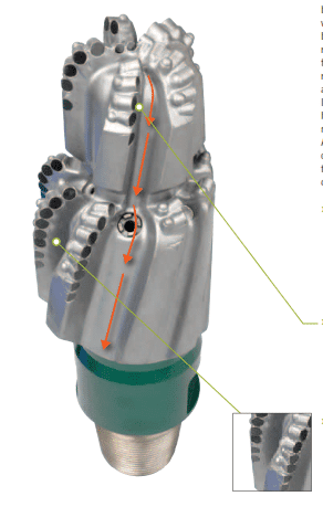
- Circulating to the bottom is preferable before tagging the bottom. The pilot bit must be in contact with the bottom of the hole to be anchored to the formation, and the reamer section can pivot around the wellbore and enlarge the hole once the rotation is started.
- Use low weight on bit (drilling conditions dictate) and 80 to 100 RPM on rotary applications and 30 to 60 rotary on motor applications with total flow rates to establish a new bottom hole pattern.
- Record pump strokes and standpipe pressure and compare with expected vs. actual hydraulics.
- Slowly break the bit in, drilling at least three (3) feet in this manner.
- Increase rotary speeds and add weight in 2,000-pound increments to determine the optimum drilling weight on the bit.
- Perform drill-off tests to determine optimum drilling parameters. Care should be taken with large diameter Bi-Center drill bits to determine maximum rpm to avoid heat damage to the reamer section. (formation hardness dictates) If in doubt, contact your local DPI representative for recommendations.
Drilling Ahead
- Before and after making connections, observe the following guidelines:
- Check pump strokes and standpipe pressure.
- After connections, add weight slowly to attain the previous weight on bit and maintain the previous parameters.
- Rotary and weight on bit parameters should be adjusted to maintain optimum drilling parameters as formation changes, directional requirements, and hole conditions.
PDC / Bi Center in Formation
| Cutter Size | Depth of cut | Rotary Min. RPM | Motor & Rotary Rotary/ Min. Mtr. / Min. Bit |
| 3/8” – 8mm | .15” | 140 | 30-140 / 140 / 170 |
| 1/2” – 13mm | .20” | 110 | 30-140 / 130 / 160 |
| 3/4” – 19mm | .30” | 100 | 30-140 / 120 / 150 |
Reaming
- Reaming long sections of the undergauge hole is not recommended but has been accomplished with varying degrees of damage to the bit.
- If reaming is necessary, observe the following guidelines:
Without a Mud Motor
- Ream with full flow.
- Use 40 to 60 RPM and 2,000 to 4,000 lbs. weight on the bit.
- Ream slowly and avoid high torque.
With a Mud Motor
- Ream with full flow.
- Use 20 to 40 RPM in low dogleg situations, use 20 to 40 RPM.
- In high dogleg situations, keep the toolface aligned to the hole direction and do not rotate.
- For either case, use only 2,000 to 4,000 lbs. weight on the bit and ream slowly to avoid high torque and possible sidetracking of the hole.
Guidelines To Prevent Bi-Center Drill Bit Balling
Bit Balling is a severe problem that may cause pulling out of holes and waste much of the rig time, especially in high-depth wells.
- Find out if there were any previous tight spots. If so, circulate with as much flow as possible through these intervals.
- Establish a new bottom-hole pattern.
- In sticky (Gumbo) type formations, keep the pumps on at full throttle whenever the drill string moves (connections and short trips).
- Pump Low/High (Thin/Thick) viscosity sweeps as necessary to keep the wellbore clean of cuttings (especially true when drilling with Bi Center drill bits).
- Keep WOB constant; don’t let the weight drill off. Avoid unnecessary fluctuations of drilling weight. A constant-steady feed of weight to bit is preferable to the drilling methods used with roller cone drill bits.
- After connections and short trips, proceed to the bottom cautiously and avoid spudding the bit. Again, ensure the pumps are at full throttle when encountering the bottom of the hole. Dropping the kelly quickly and then stopping the drill string suddenly can cause the bit to hit the bottom and damage or balled due to pipe stretch.
- Review previous offset bit records, morning reports, mud logs, and other related information to locate sticky/balling intervals.
- Optimize hydraulics to provide maximum flow rate. Changing liners to increase available standpipe pressure, using a rotor nozzle with a motor, using larger drill pipe O.D. (API drill pipe specs), and minimizing the number of drill collars design (increasing heavy-weight drill pipe) are possible alternatives to increase available flow rates in marginal flow applications.
Guidelines For Bit Cleaning With Bi-Center Drill Bits
Bit balling sometimes occurs when drilling in soft/sticky formations with a water base drilling fluid. The usual indications are a sudden decrease in the penetration rate and rotary torque and an increase in on-bottom standpipe pressure (which disappears when off-bottom).
Cleaning the bit
To clean the bit, raise the bit off-bottom, and then return to just above the bottom while running complete pumps and average bit speed. The bit should be held there for 10 to 15 minutes, giving the fluid flow across the bit face an opportunity to clean the bit face while no new cuttings are generated. High rotary speeds off-bottom for short periods while circulating can be tried to “sling” the balled-up formation off the bit face. WARNING: This may cause holes with an angle to undercut or wash on the low side.
If balling continues to be a problem and the flow rate of the drilling fluid cannot be increased, it might be best to limit the penetration rate to one where balling is not a problem. If repeated cleaning is needed or the penetration rate falls to the point where the bit can no longer drill economically, it will be advisable to pull the bit. Other bit styles designed for better cleaning should then be considered.
Nozzle Plugging
If a nozzle becomes plugged, the indication is an increase in standpipe pressure with the same amount of flow previously. One method is to use the same circulation technique as described above. Another method of cleaning a plugged nozzle is to lift the bit 30 to 40 feet off-bottom, then drop the kelly 5 to 10 feet and stop it suddenly to surge the fluid through the bit.
If it is impossible to clear the nozzle, but the bit still drills at an acceptable penetration rate and no other problem is experienced, it should be left on the bottom. Bits with a single plugged nozzle often make economic runs, and plugging material will sometimes wash away given time. The pumping of nut plug (Lost Circulation Material), Low/High (Thin/Thick) viscosity sweeps will also aid in unplugging nozzles and bit face balling.
Bi-Center Directional Tendencies
For Build, Hold, Or Drop Runs Utilizing Rotary Speed To Control Inclination.
- For Building, Optimum Rotary Speed will be 30-40 RPM
- Optimum Rotary Speed for Hold-40-50 RPM
- In case Of dropping, the Optimum Rotary Speed will be 50-60 RPM
| BI CENTER SIZE | STABILIZER SIZE | % DRILL SIZE |
| 17” X 20” | 14.5 | 72 |
| 14.5” X 17.5” | 13 | 74 |
| 12.25” X 14.75” | 11.5 | 78 |
| 12.25” X 13.5” | 10.5 | 78 |
| 10.625” X 11.5” | 9.25 | 80 |
| 10.625” X 12.25” | 10 | 82 |
| 8.5” X 9.875” | 8.25 | 84 |
| 6.5” X 7.5” | 6.5 | 86 |
| 6” X 7” | 6 | 86 |
Note: a high % of the runs, this data was extracted from utilized performance motors in the 30’ range. The more successful runs placed the stabilizer 40 to 60 ft. Using a 1.75° or greater bent housing motor and a minimum motor speed of 120 rpm from the bit.
Suggested Operating Parameters are based on case histories and have provided proven results. Recommendations are, however, general guidelines only and will vary with application. DPI assumes no liability for the use of recommendations or suggestions contained herein.